Power supply system

a power supply system and power supply technology, applied in the direction of dc-ac conversion without reversal, battery/fuel cell control arrangement, capacitor propulsion, etc., can solve the problems of excessive dischargeable power of the overall power supply system or a charge excessive dischargeable power etc., to achieve the effect of efficiency of the overall power supply system

Active Publication Date: 2017-01-12
TOYOTA JIDOSHA KK
View PDF12 Cites 3 Cited by
  • Summary
  • Abstract
  • Description
  • Claims
  • Application Information

AI Technical Summary

Benefits of technology

[0005]However, when only the distribution ratios are determined on the basis of the ratio of available charge energies and the ratio of available discharge energies, there may occur a situation that the efficiency of the overall power supply system does not become optimal. Specifically, when only the distribution ratios are determined on the basis of the ratio of available charge energies and the ratio of available discharge energies, there may occur a situation that a dischargeable power of the overall power supply system or a chargeable power of the overall power supply system is excessively limited. In other words, for the method of determining the distribution ratios, described in JP 2009-261183 A, there may be room for improvement in terms of suitably ensuring a dischargeable power of the overall power supply system or a chargeable power of the overall power supply system.

Problems solved by technology

However, when only the distribution ratios are determined on the basis of the ratio of available charge energies and the ratio of available discharge energies, there may occur a situation that the efficiency of the overall power supply system does not become optimal.
Specifically, when only the distribution ratios are determined on the basis of the ratio of available charge energies and the ratio of available discharge energies, there may occur a situation that a dischargeable power of the overall power supply system or a chargeable power of the overall power supply system is excessively limited.
As a result, particularly, after the dischargeable power of each individual electrical storage device has begun to be limited, there may occur a situation that the dischargeable power of the overall power supply system is excessively limited.

Method used


Image

  • Power supply system
  • Power supply system
  • Power supply system

Examples


Embodiment Construction

[0061]Hereinafter, an embodiment of a case where the power supply system according to the invention is applied to a vehicle 1 including a motor generator 10 will be described as an example of a mode for carrying out the invention with reference to the accompanying drawings. The power supply system according to the invention may be applied to not only the vehicle 1 including the motor generator 10 but also any device that utilizes electric power that is supplied from the power supply system.

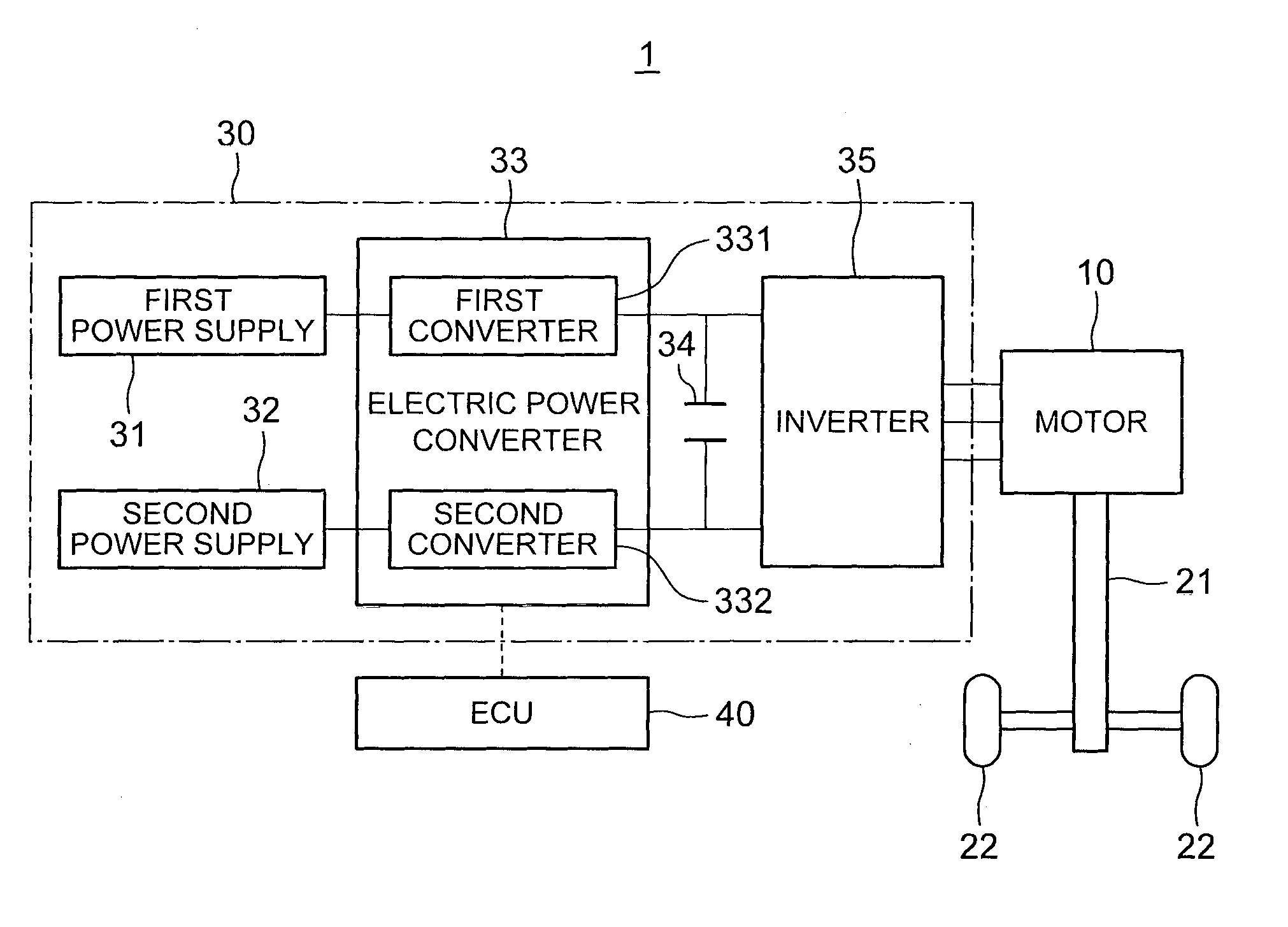
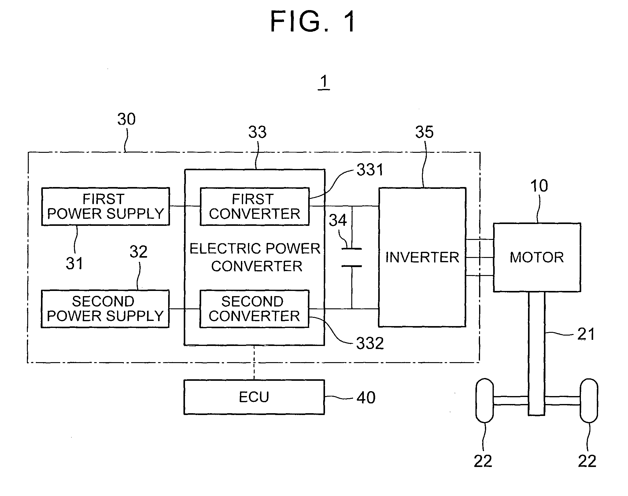
[0062]The configuration of the vehicle 1 according to the present embodiment will be described with reference to FIG. 1. FIG. 1 is a block diagram that shows an example of the configuration of the vehicle 1 according to the present embodiment.

[0063]As shown in FIG. 1, the vehicle 1 includes the motor generator 10, an axle 21, wheels 22, a power supply system 30, and an electronic control unit (ECU) 40. The ECU 40 is one specific example of a “power supply control apparatus (that is, including sett...


PUM


Abstract

A power supply system includes a plurality of electrical storage devices, a distributor configured to distribute electric power between the plurality of electrical storage devices in a desired distribution mode, and an electronic control unit. The electronic control unit configured to (i) set the desired distribution mode based on at least one of a magnitude relation between first rates of change in dischargeable power of the corresponding electrical storage device to a charge state value indicating a remaining level of charge of the corresponding electrical storage device, or a magnitude relation between second rates of change in chargeable power of the corresponding electrical storage device to the charge state value, and (ii) control the distributor such that electric power is distributed in the set distribution mode.

Description

BACKGROUND OF THE INVENTION[0001]1. Field of the Invention[0002]The invention relates to a technical field of a power supply system including a plurality of electrical storage means.[0003]2. Description of Related Art[0004]There is known a power supply system including a first electrical storage device, a second electrical storage device and a converter that distributes electric power between these first electrical storage device and second electrical storage device (see, for example, Japanese Patent Application Publication No. 2009-261183 (JP 2009-261183 A)). The first electrical storage device and the second electrical storage device each are, for example, a rechargeable direct-current power supply, such as a secondary battery and a capacitor. Particularly, a power supply system described in JP 2009-261183 A determines a distribution ratio in the following manner. The distribution ratio is the ratio of electric power that is distributed to the first electrical storage device and e...

Claims


Application Information

Patent Timeline
Patent Type & Authority Applications(United States)
IPC IPC(8): B60L11/18H02P4/00H02J7/00B60L11/08H02M3/08H02M7/44B60L50/13H02J7/02
CPCB60L11/1861H02M3/08H02M7/44H02P4/00B60L11/1809B60L11/08H02J7/0068B60L15/2045B60L2240/547B60L50/40B60L53/00B60L58/12B60L58/20B60L50/13Y02T10/64Y02T10/70Y02T10/7072Y02T10/72Y02T90/14
Inventor ANDO, TORUHIRAI, MAKOTO
Owner TOYOTA JIDOSHA KK
Why Eureka
Try Eureka