Power supply apparatus

a power supply apparatus and power supply technology, applied in the direction of power supply for data processing, dc source parallel operation, instruments, etc., can solve the problems of reducing the efficiency of the whole power supply apparatus 100/b>, generating much more ineffective power, and not conducive to power saving, so as to improve the conversion efficiency of the buck power conversion circuit, the effect of improving the efficiency of the power supply apparatus

Inactive Publication Date: 2013-02-21
3Y POWER TECH TAIWAN
View PDF4 Cites 19 Cited by
  • Summary
  • Abstract
  • Description
  • Claims
  • Application Information

AI Technical Summary

Benefits of technology

[0016]From the above, in the present invention, the switching unit is used to output the auxiliary power to the buck power conversion circuit for generating the standby power in the activation state of the power supply apparatus. In addition, in the operation state of the power supply apparatus, the switching unit outputs the main power to the buck power conversion circuit for generating the standby power. Since the auxiliary power conversion circuit is completely operated only in the activation state of the power supply apparatus, the whole efficiency of the power supply apparatus (just for the activation state of the power supply apparatus) is improved because of the superior conversion efficiency of the buck power conversion circuit (about 93% to 97%). Thus, the power supply may not generate much ineffective power and it is conducive to power saving.

Problems solved by technology

However, the circuit topology (configuration) of the auxiliary power conversion circuit 130 is generally the flyback power conversion circuit, such that the whole efficiency of the power supply apparatus 100 may reduce due to the inferior conversion efficiency of the flyback power conversion circuit (about 70% to 75%).
Thus, the power supply apparatus 100 may generate much more ineffective power and it is not conducive to power saving.

Method used


Image

  • Power supply apparatus
  • Power supply apparatus
  • Power supply apparatus

Examples


Embodiment Construction

[0026]Descriptions of the invention are given with reference to the exemplary embodiments illustrated with accompanied drawings, wherein same or similar parts are denoted with same reference numerals. In addition, whenever possible, identical or similar reference numbers stands for identical or similar elements in the figures and the embodiments.

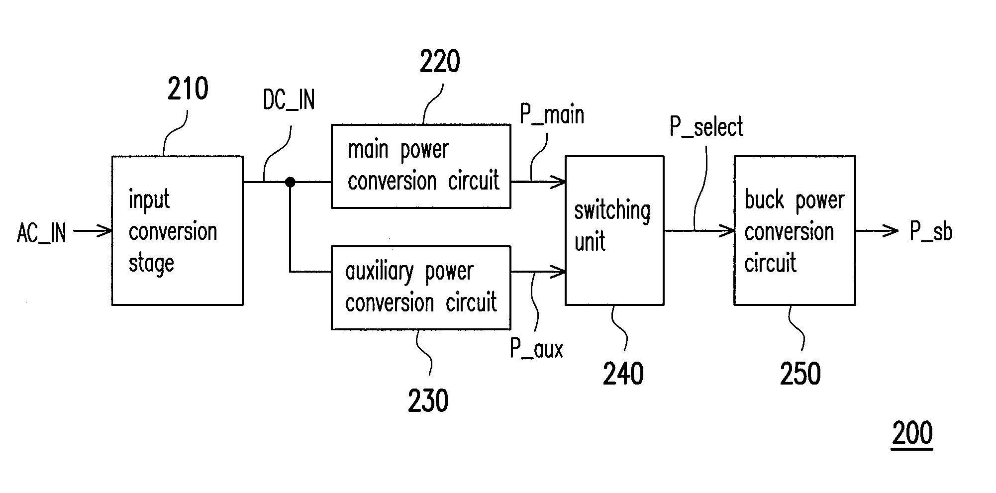
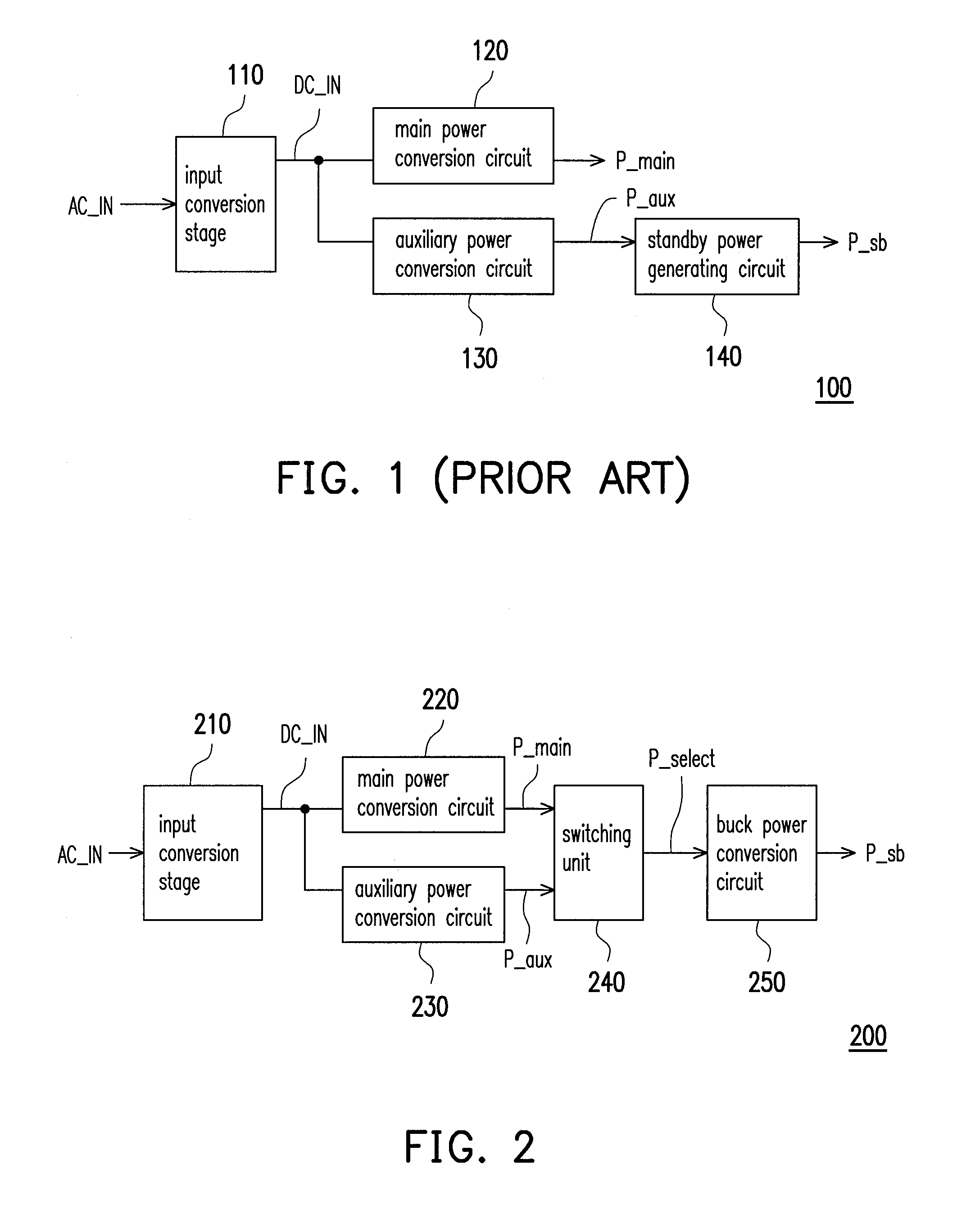
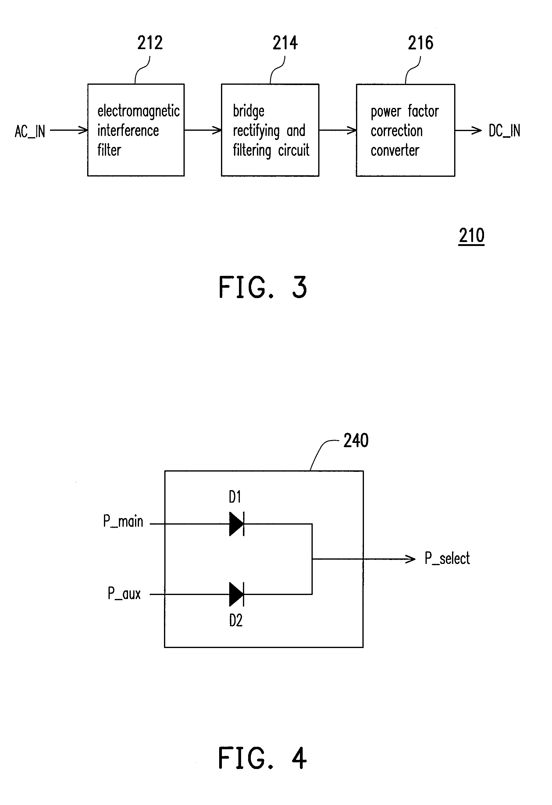
[0027]FIG. 2 is a diagram of a power supply apparatus 200 according to an embodiment of the present invention. Referring to FIG. 2, the power supply apparatus 200 is applicable to a computer system, but not limited thereto. The power supply apparatus 200 includes an input conversion stage 210, a main power conversion circuit 220, an auxiliary power conversion circuit 230, a switching unit 240 and a buck power conversion circuit 250. In the embodiment, the input conversion stage 210 is used to receive an AC voltage AC_IN (e.g., city power, but not limited thereto) and convert the AC voltage AC_IN to output a DC input voltage DC_IN.

[0028]More ...


PUM


Abstract

A power supply apparatus is provided, which includes an input conversion stage, a main power conversion circuit, an auxiliary power conversion circuit, a switching unit and a buck power conversion circuit. The input conversion stage is used for receiving an AC voltage and converting the AC voltage to output a DC input voltage. The main power conversion circuit is used for converting the DC input voltage so as to generate and output a main power. The auxiliary power conversion circuit is used for converting the DC input voltage so as to generate and output an auxiliary power. The switching unit is used for receiving the main power and the auxiliary power and selecting and outputting one of the main power and the auxiliary power. The buck power conversion circuit is used for stepping down the output of the switching unit so as to generate and output a standby power.

Description

CROSS-REFERENCE TO RELATED APPLICATION[0001]This application claims the priority benefit of Taiwan application serial no. 100129764, filed on Aug. 19, 2011. The entirety of the above-mentioned patent application is hereby incorporated by reference herein and made a part of this specification.BACKGROUND OF THE INVENTION[0002]1. Field of the Invention[0003]The present invention relates to a power supplying technique, and more particularly, to a power supply apparatus applicable to a computer system.[0004]2. Description of Related Art[0005]FIG. 1 is a diagram of a conventional power supply apparatus 100 of a computer system. Please refer to FIG. 1. The power supply apparatus 100 includes an input conversion stage 110, a main power conversion circuit 120, an auxiliary power conversion circuit 130 and a standby power generating circuit 140. Herein the input conversion stage 110 is used to receive an AC voltage AC_IN and convert the received AC voltage to output a DC input voltage DC_IN. ...

Claims


Application Information

Patent Timeline
Patent Type & Authority Applications(United States)
IPC IPC(8): G05F1/563
CPCH02J1/10G06F1/26
Inventor LIU, CHANGE-YUANWANG, CHUAN-KAI
Owner 3Y POWER TECH TAIWAN
Why Eureka
Try Eureka