Combustion controlling device

US20170276352A1Active Publication Date: 2017-09-28YAMATAKE HONEYWELL CO LTD
2 Cites 0 Cited by

Patent Information

Authority / Receiving Office
US · United States
Current Assignee / Owner
Publication Date
2017-09-28

Smart Images

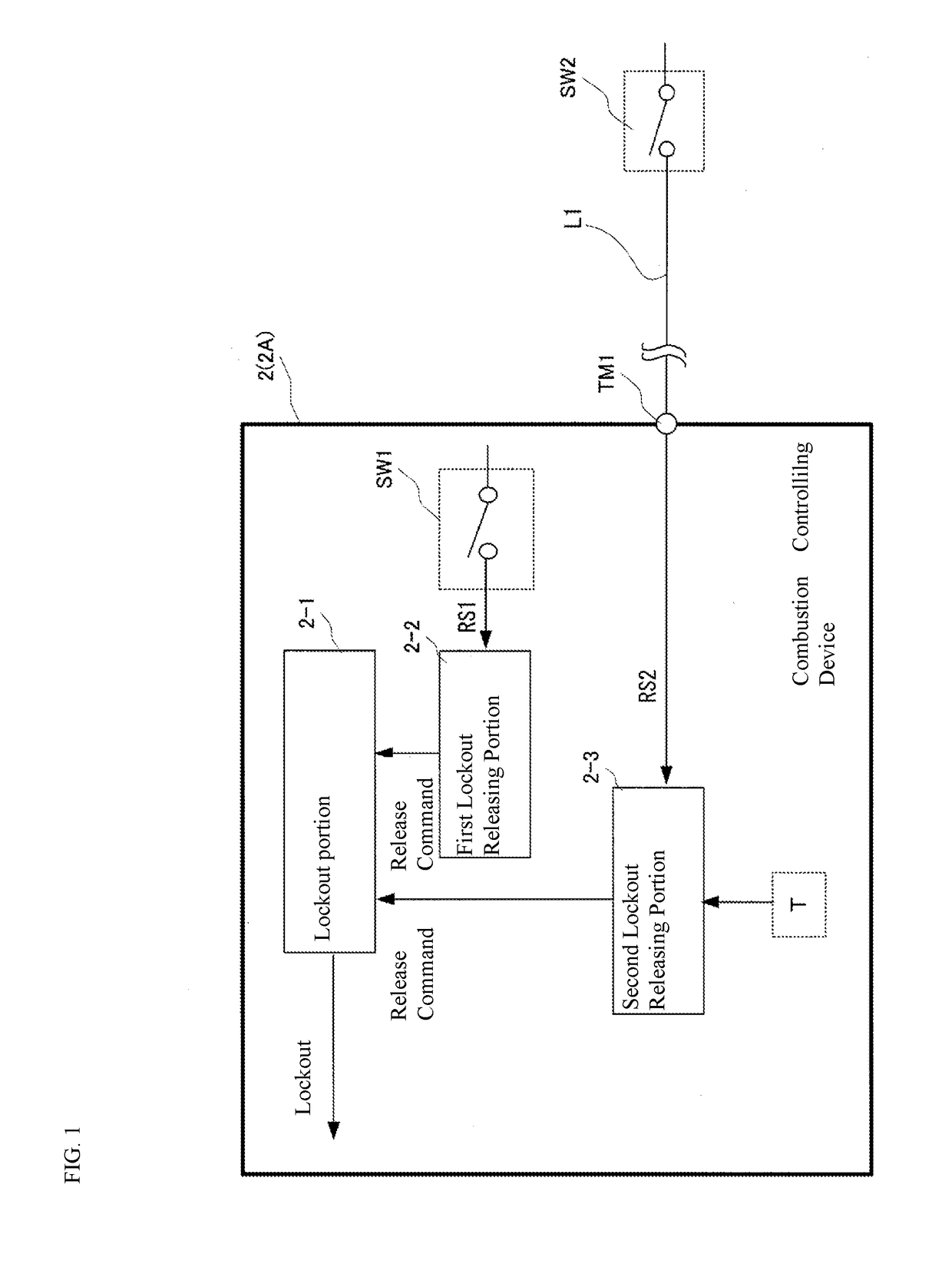
  • Figure 1
    Figure 1
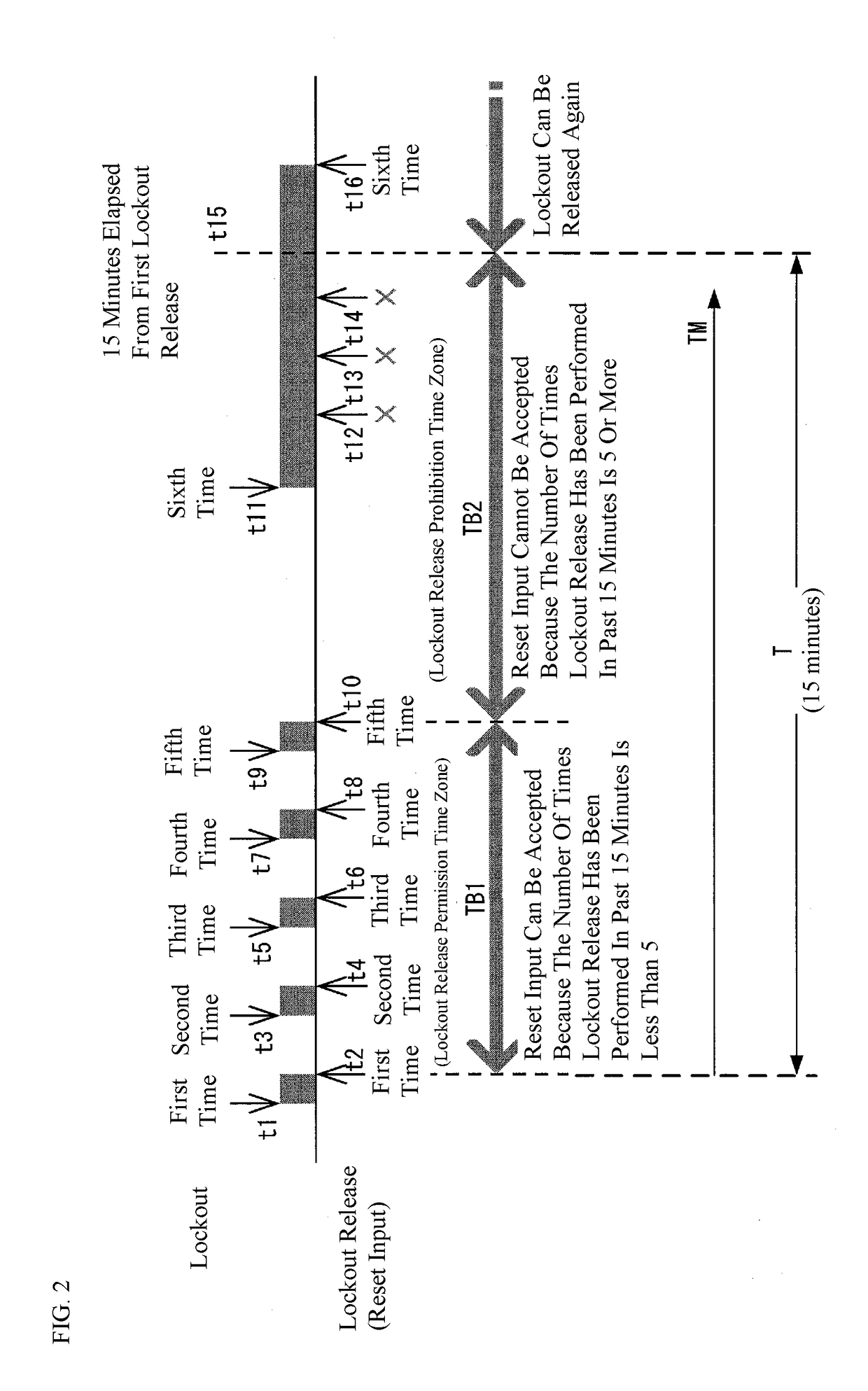
  • Figure 2
    Figure 2
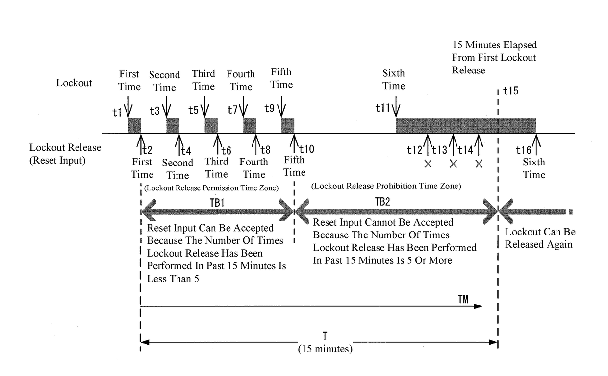
  • Figure 3
    Figure 3
Patent Text Reader

Abstract

A first reset switch is attached to a combustion controlling device. A second reset switch is installed at a remote place distant from the combustion controlling device. A first reset input from the first reset switch is received without any restriction to release the lockout. A reset input from the second reset switch is received with any restriction to release the lockout. Specifically, when the lockout releases are performed for a predetermined number of times or more upon receiving the reset input before a predetermined time elapses after the lockout has been released upon receiving the initial reset input, the release of the lockout upon receiving the reset input is prohibited until the predetermined time elapses.
Need to check novelty before this filing date? Find Prior Art

Description

CROSS-REFERENCE TO RELATED APPLICATION

[0001] This application claims priority to Japanese Application No. 2016-063540 filed on Mar. 28, 2016. This application is incorporated herein in its entirety.TECHNICAL FIELD

[0002] The present invention relates to a combustion controlling device that controls the operation of a combustion device.BACKGROUND

[0003] FIG. 6 illustrates an example of a combustion system using a combustion controlling device that controls the operation of a combustion device (see, for example, Japanese Unexamined Patent Application Publication No. 2011-208921). A combustion system 100 includes combustion equipment 1, a combustion controlling device 2 (2B), a fuel flow channel 3, and an air flow channel 4.

[0004] The combustion equipment 1 includes a combustion chamber 5, a main burner 6 for heating an interior of the combustion chamber 5, a pilot burner 7 for igniting the main burner 6, an ignition device (IG) 8 for igniting the pilot burner 7, a flame detector 9 for detec...

Examples

Embodiment Construction

[0034]An example of the invention will be described in detail below with reference to the drawings. FIG. 1 is a diagram illustrating a main portion of a combustion controlling device 2 (2A) according to an example of the present invention.

[0035]The combustion controlling device 2 (2A) is configured by hardware including a processor and a memory device and a program achieving various types of functions in cooperation with the hardware. The functions of the combustion controlling device 2 (2A) and the conventional combustion controlling device 2 (2B) illustrated in FIG. 6 are partly different from each other.

[0036]FIG. 1 illustrates only functional portions of the combustion controlling device 2 (2A) which are noteworthy in the present example. In addition, a basic configuration of a combustion device whose operation is controlled by the combustion controlling device (2A) refers to the configuration of the combustion device 19 illustrated in FIG. 6.

[0037]The combustion controlling dev...