Shoulder arthroplasty implant system

a technology for implanting systems and shoulder joints, applied in shoulder joints, surgery, medical science, etc., can solve the problems of increased blood loss, increased complication rate, and difficulty in stem removal

Active Publication Date: 2017-10-26
INTEGRATED SHOULDER COLLABORATION INC
View PDF1 Cites 41 Cited by
  • Summary
  • Abstract
  • Description
  • Claims
  • Application Information

AI Technical Summary

Benefits of technology

[0021]The concave taper may be defined by at least one radius revolved around a central axis of the cylindrical extrusion. The implant may further comprise a first fin extending radially outward from the bone contacting surface. The first fin may be configured to provide rotational stability and tapering from the proximal portion toward the distal portion. The first fin may have a width adjacent the proxima

Problems solved by technology

Removal of the stem is technically difficult, associated with longer operative times, increased blood loss, and higher complication rates.
The adaptor trays used in these onlay designs are not always ideal because they add thickness in the joint that is potentially undesirable.
Over-tensioning the joint can lead to decreased range of motion and also can cause acromial fractures, which are difficult to treat.
Nonetheless, these are not the only complications that that can arise with current shoulder implants.
This may lead to a decrease in the physiologic loads in the proximal aspect of the humerus.
Without this load, bone loss in this area can occur and

Method used


Image

  • Shoulder arthroplasty implant system
  • Shoulder arthroplasty implant system
  • Shoulder arthroplasty implant system

Examples


Embodiment Construction

[0061]Before the present subject matter is further described, it is to be understood that this subject matter described herein is not limited to particular embodiments described, as such may of course vary. It is also to be understood that the terminology used herein is for the purpose of describing particular embodiments only, and is not intended to be limiting. Unless defined otherwise, all technical terms used herein have the same meaning as commonly understood by one skilled in the art to which this subject matter belongs.

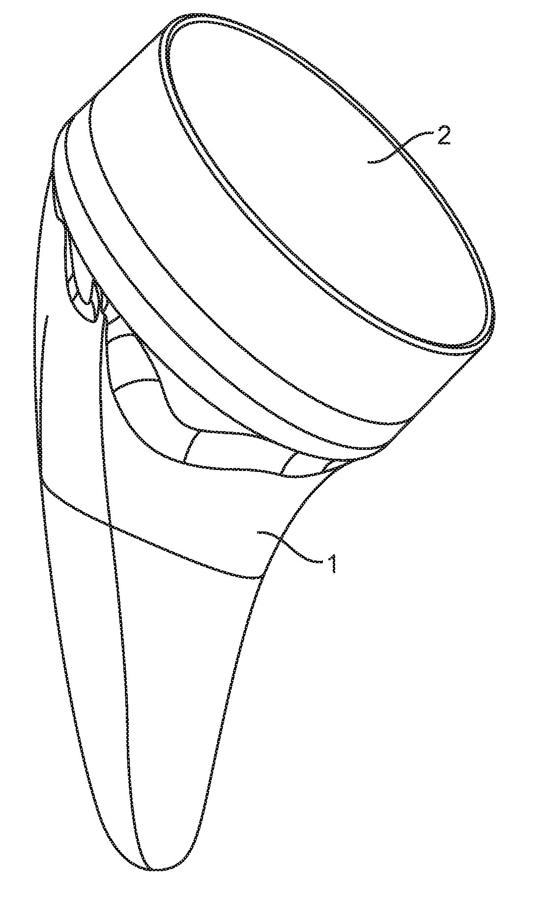
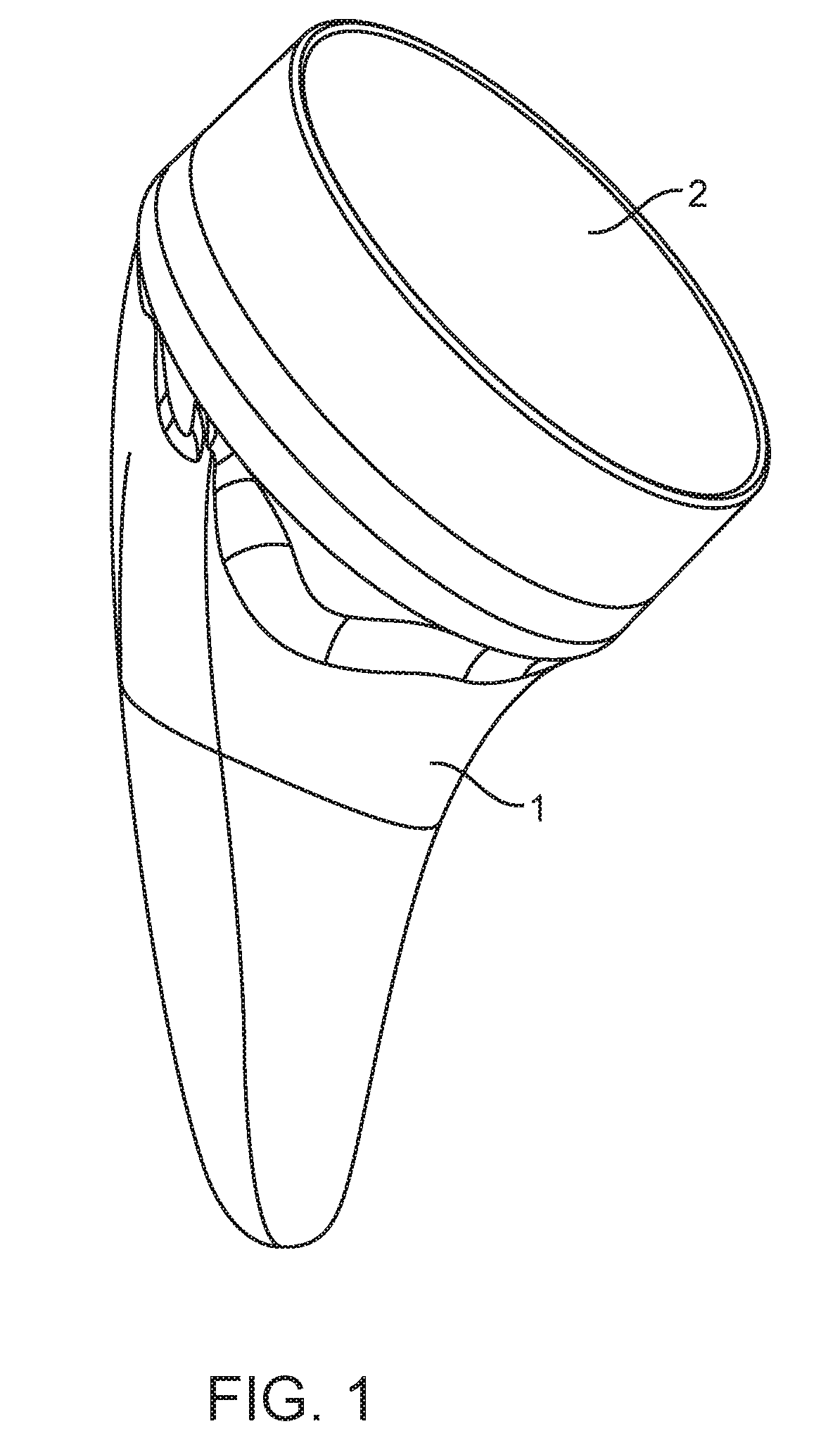
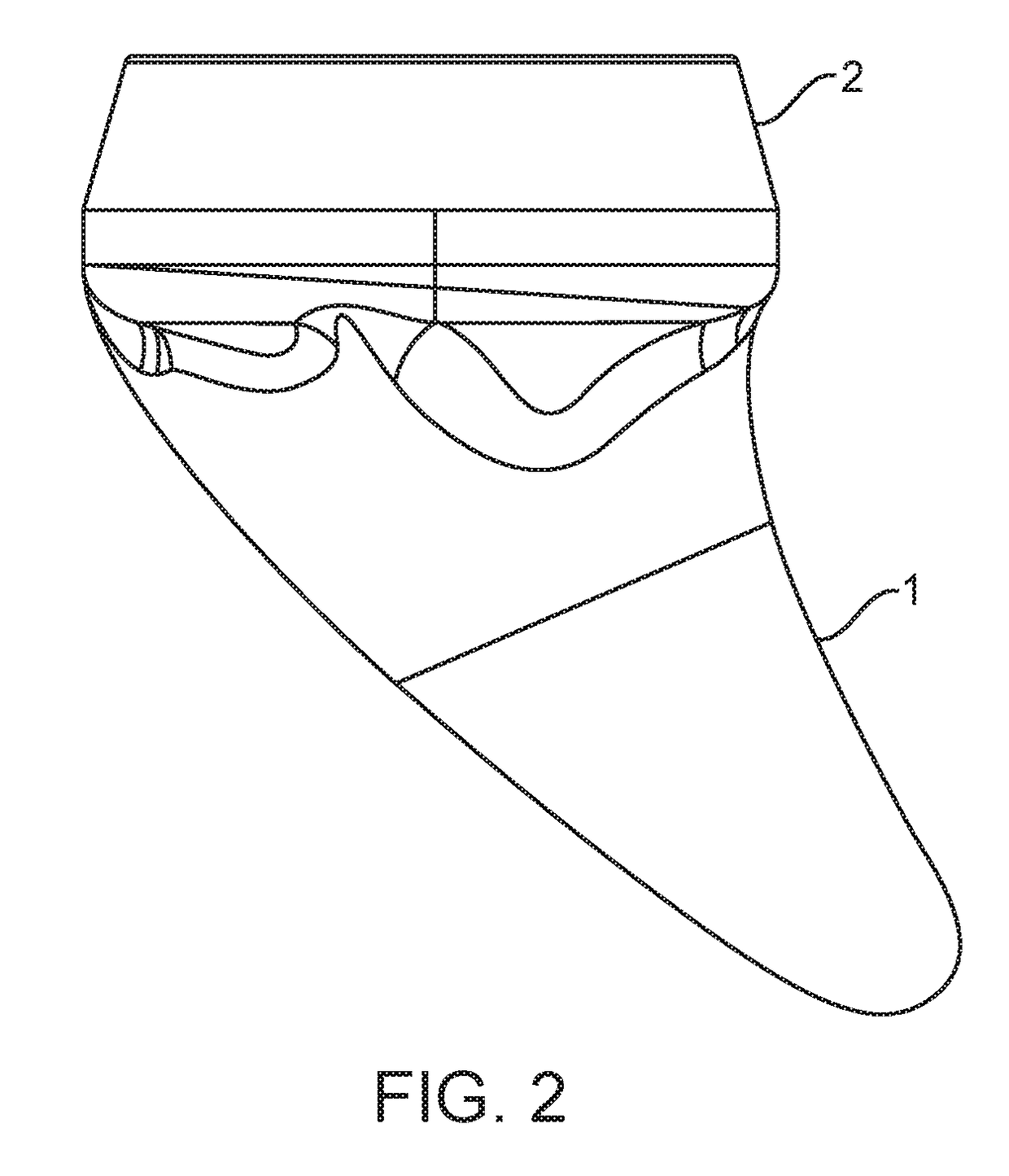
[0062]Disclosed is a shoulder arthroplasty system that is optionally convertible in use between an anatomic and a reverse shoulder implantation configuration. The system includes a short stem prosthesis that may provide several advantages. In the reverse shoulder configuration, the system includes an articular surface cup arranged in an inlay configuration on a receptacle of the stem. This may provide for a much more compactly sized system with respect to an on...


PUM


Abstract

An implant for shoulder arthroplasty includes a stem and optionally a head component or a cup component. The stem is sized and shaped to fit into an intramedullary canal of the humerus. The proximal portion of the stem has a concave taper and the distal portion of the stem has a taper. The distal taper includes an anterior-posterior taper and a medial-lateral taper. The shape of the stem loads the metaphysis of the humerus with a greater load than the load applied to the diaphysis of the humerus.

Description

CROSS-REFERENCE TO RELATED APPLICATIONS[0001]The present application is a non-provisional of, and claims the benefit of U.S. Provisional Patent Application No. 62 / 300,853 (Attorney Docket No. 44057-715.101) filed Feb. 28, 2016; the entire contents of which are incorporated herein by reference.BACKGROUND OF THE INVENTION[0002]Shoulder replacement surgeries were first performed in the 1950's in the United States to treat severe shoulder fractures. Over the years, the implants used in shoulder replacement surgeries have been improved to provide better outcomes and to expand the clinical indications for use to include shoulder arthroplasty for degenerative conditions. Modern shoulder replacement implants are generally of two designs; anatomic and reverse.[0003]The anatomic shoulder implants are intended to restore the natural kinematics of the shoulder by replacing the humeral head and glenoid with similarly shaped prosthetic designs that recreate normal anatomy. The anatomic shoulder i...

Claims


Application Information

Patent Timeline
IPC IPC(8): A61F2/40A61B17/68A61F2/30A61F2/46
CPCA61F2/40A61B17/68A61F2/4612A61F2002/30331A61F2002/30332A61F2/30A61B17/1659A61B17/1684A61B17/1778A61F2/4003A61F2/4059A61F2002/2835A61F2002/305A61F2002/30841A61F2002/30884A61F2002/4022A61F2/28
Inventor HATZIDAKIS, ARMODIOS M.HOENECKE, JR., HEINZ R.JACOBSON, SCOTT R.KELLY, II, JAMES D.MILLER, DREWD'LIMA, DARRYLSKINNER, NATHANIEL E.
Owner INTEGRATED SHOULDER COLLABORATION INC
Why Eureka
Try Eureka