Emergency limb fixation or restraining device

Pending Publication Date: 2018-06-14
SCHLESINGER YOEL
View PDF8 Cites 1 Cited by
  • Summary
  • Abstract
  • Description
  • Claims
  • Application Information

AI Technical Summary

Benefits of technology

[0006]It is accordingly an object of the present invention to provide a splint device and method of use thereof for injured limb or body part fixation for animal or human patients for u

Problems solved by technology

Such fixation requires training for proper deployment and involves inordinate amounts of time while an injured person must painfully maintain a non-moving position.
In addition to the drawbacks recited above, the length of a typical splint is often too large to be carried in a trauma jump bag/kit used by EMTs and requires separate awkward transport.
Many splint devices have been described in the past with cuffs and rotatable p

Method used


Image

  • Emergency limb fixation or restraining device
  • Emergency limb fixation or restraining device
  • Emergency limb fixation or restraining device

Examples


Embodiment Construction

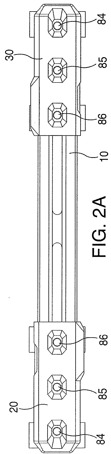
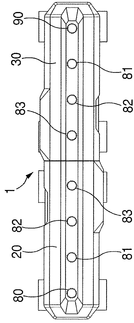
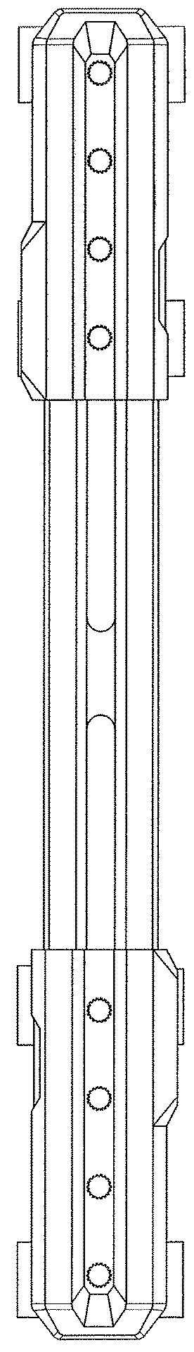
[0057]With reference to the drawings, FIG. 1 shows the splint device 1 in the minimal closed position, as generally used for stowing the splint device in an EMS bag / kit. Riding members 20 and 30, which are longitudinally movable relative to each other, are shown abutted with one another in a closed or minimal length position. As shown, each of the riding members 20 and 30 has four apertures 80-83, used for connection to a belt member for connection to a patient, as shown in FIGS. 1, 2b, 4, 6a, 6b, and 10. Riding members with three apertures 84-86 are shown in FIGS. 2a, 7, and 19.

[0058]Riding members 20 and 30 are shown as slidingly seated on track member 10, in FIGS. 2a, 2b, 3 and 4, with riding members 20 and 30, being identical in structure and positioned on track member 10, in mirror image placement. Button 25 in FIG. 7, on riding member 20 (riding member 30, which is structurally identical to riding member 30 has a similar button, which is not visible) activates and deactivates ...


PUM


Abstract

A method of splinting limbs of a patient by a single person and an elongated splint device, for use in the method. The splint device has a first track member and second and third elongated riding members movably held and positioned on the first track member. The riding members are freely movable on the first track member along a single longitudinal axis to obtain a proper length for splinting and a releasable locking mechanism is included to maintain the selected length. Two or more adjustable belt elements are removably connected to the riding member and serve to affix the splint device to a patient in a proper splinting position.

Description

[0001]This application is a continuation in part of U.S. patent application Ser. No. 14 / 568,344, filed Dec. 9, 2014, the entire disclosure of which is incorporated herein by reference thereto.FIELD OF THE INVENTION[0002]This invention relates to splints and fixation or restraining devices for preventing increased trauma by restraining movement of limbs or other body parts of living beings including animals and humans and relates particularly to devices for use in emergency field situations for position fixing of arms and legs around elbow and knee joints by EMS personnel.BACKGROUND OF THE INVENTION[0003]When a person fractures (or breaks) a limb and requires emergency handling and treatment prior to hospitalization, EMS (emergency medical services) or other medical personnel generally must provide rapid and temporary limb immobilization in the condition, as found, in order to ensure that no further injuries and tissue injuries occur. A basic splint used for such emergency purpose is...

Claims


Application Information

Patent Timeline
IPC IPC(8): A61F5/058
CPCA61F5/05825A61F5/05858A61F5/0585A61F5/058A61F2005/0158
Inventor SCHLESINGER, YOEL
Owner SCHLESINGER YOEL
Why Eureka
Try Eureka