
Eye imaging apparatus with a wide field of view and related methods

a wide-field, eye imaging technology, applied in the field of eye imaging apparatus, can solve the problems of eye diseases and vision loss in general, eye diseases and vision problems among children, especially new-born babies, can have severe and far-reaching consequences, and the visual centers in the brain are not fully mature, so as to reduce or eliminate the possibility of cross-contamination among patients, prevent vision loss, and facilitate operation

Inactive Publication Date: 2015-05-28
VISUNEX MEDICAL SYST
View PDF3 Cites 5 Cited by
  • Summary
  • Abstract
  • Description
  • Claims
  • Application Information

AI Technical Summary

Benefits of technology

The present invention is related to an eye imaging apparatus: it is small, portable, and easy to operate, making it suitable for in-home use. Additionally, it is hermetically sealed, meaning it can withstand sterilization procedures, which reduces the risk of cross-contamination between patients. The technical effects of this invention include improved treatment and prevention of vision loss, as well as opportunities for physical development and educational progress for small children in rural areas.

Problems solved by technology

Likewise, eye diseases and vision loss in general are serious problems.
Moreover, eye diseases and vision problems among children, especially new-born babies, can have severe and far-reaching implications.
For infants and small children, the visual centers in the brain are not fully mature.
Undetected eye problems in infants and others may result in irreversible loss of vision.

Method used


Image

  • Eye imaging apparatus with a wide field of view and related methods
  • Eye imaging apparatus with a wide field of view and related methods
  • Eye imaging apparatus with a wide field of view and related methods

Examples


Embodiment Construction

[0065]The present invention now will be described in detail with reference to the accompanying figures. This invention may be embodied in many different forms and should not be construed as limited to the exemplary embodiments discussed herein.

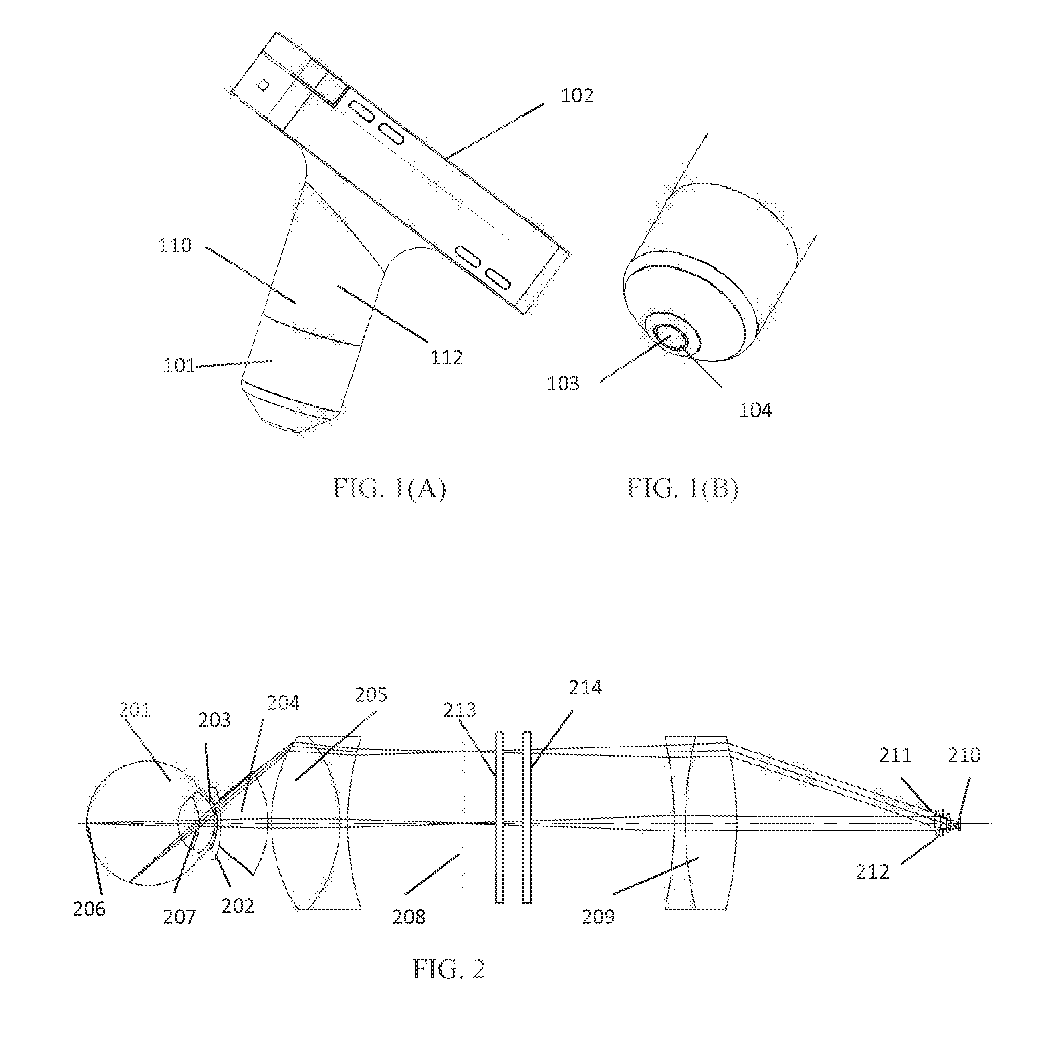
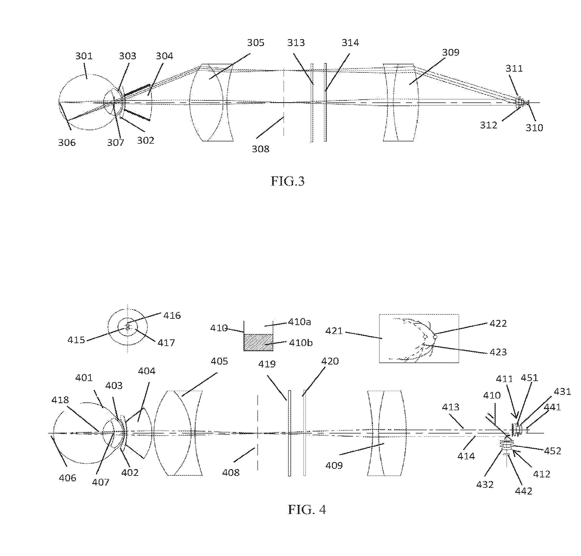
[0066]Various embodiments of the present disclosure describe an eye imaging apparatus. In some embodiments, this eye imaging apparatus has a wide field of view. The field of view, may in certain embodiments be at least 60 degree and up to 180 degree. In some embodiments, the field of view is at least 120 degrees but no more than 180 degrees. Various embodiments of the eye imaging apparatus may, for example, comprise a housing, a light source inside the housing to illuminate an eye, and an optical imaging system inside the housing. The optical imaging system may include an optical window configured to be in contact with a cornea of the eye forward the optical window, an imaging lens positioned behind the optical window and optically aligned wit...


PUM


Abstract

An eye imaging apparatus can include a housing, an optical imaging system in the housing, and a light source in the housing to illuminate an eye. The optical imaging system can include an optical window at a front end of the housing with a concave front surface for receiving the eye as well as an imaging lens disposed rearward the optical window. The apparatus can comprise a light conditioning element configured to receive light from the light source and direct said light to the eye. The apparatus can further include an image sensor in the housing disposed to receive an image of the eye from the optical imaging system. In various embodiments, light conditioning element includes at least one multi-segment surface. In some embodiments, the housing is provided with at least one hermitic seal, for example, with the optical window. In some embodiments, time sequential illumination is employed.

Description

CROSS REFERENCE TO RELATED APPLICATIONS[0001]This application is a continuation of U.S. application Ser. No. 14 / 191,291 filed Feb. 26, 2014 which is a continuation-in-part of U.S. application Ser. No. 13 / 845,069 filed Mar. 17, 2013 which claims the benefit of U.S. Provisional Application No. 61 / 612,306 filed Mar. 17, 2012, each of which is herein incorporated by reference in its entirety.INCORPORATION BY REFERENCE[0002]All publications and patent applications mentioned in this specification are incorporated herein by reference in their entirety to the same extent as if each individual publication or patent application was specifically and individually indicated to be incorporated by reference.STATEMENT AS TO FEDERALLY SPONSORED RESEARCH[0003]None.BACKGROUND[0004]Various embodiments of the invention relate generally to an eye imaging apparatus and related methods, and for example to an eye imaging apparatus with a wide field of view and related methods.[0005]Eyes are among the most v...

Claims


Application Information

Patent Timeline
Patent Type & Authority Applications(United States)
IPC IPC(8): A61B3/14A61B3/125
CPCA61B3/0008A61B3/125A61B3/14A61B3/1208A61B3/132A61B3/158A61B3/152A61B3/0025A61B3/145A61B5/0013A61B2560/0475A61B2576/02
Inventor SU, WEI
Owner VISUNEX MEDICAL SYST
Learn More