Coupling a plurality of user entities in a communication network

a communication network and user technology, applied in the field of user entities in the communication network, can solve the problems of increasing the exposure to attacks, increasing the latencies and jitters, and reducing the reliability and availability of the overall communication system

a communication network and user technology, applied in the field of user entities in the communication network, can solve the problems of increasing the exposure to attacks, increasing the latencies and jitters, and reducing the reliability and availability of the overall communication system

US20180332642A1Inactive Publication Date: 2018-11-15SIEMENS AG

Image

  • Coupling a plurality of user entities in a communication network
  • Coupling a plurality of user entities in a communication network
  • Coupling a plurality of user entities in a communication network

Examples


Embodiment Construction

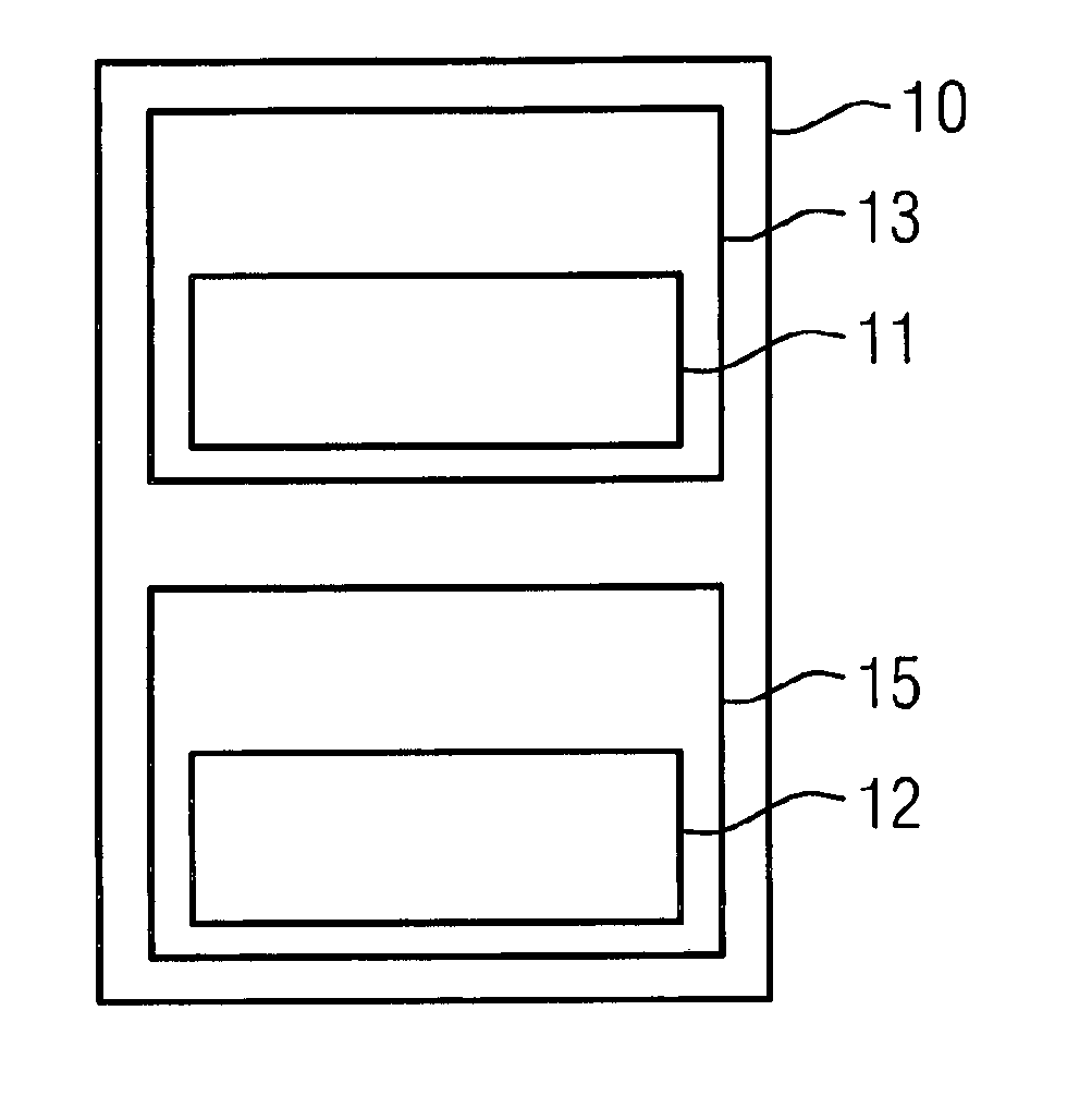
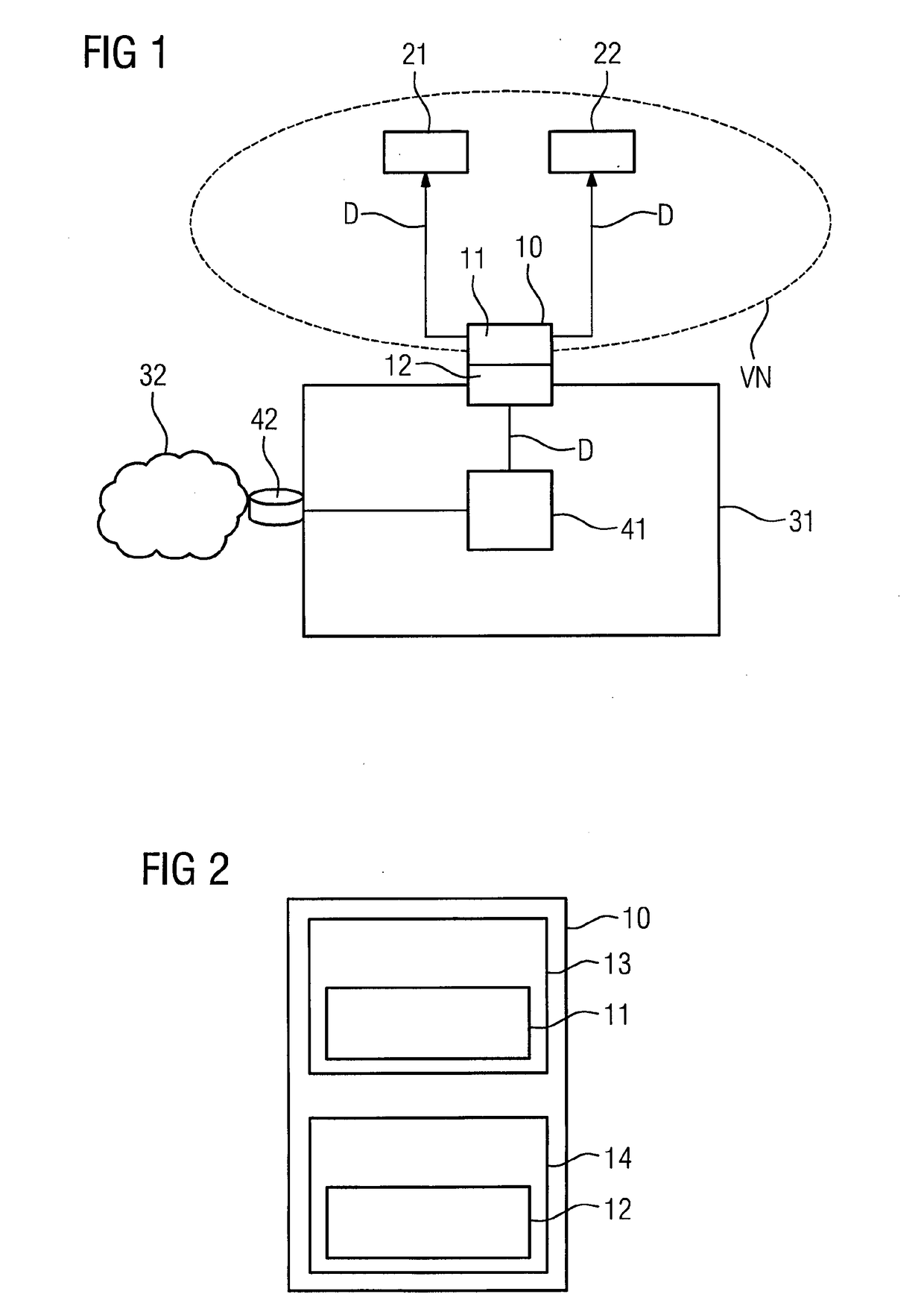
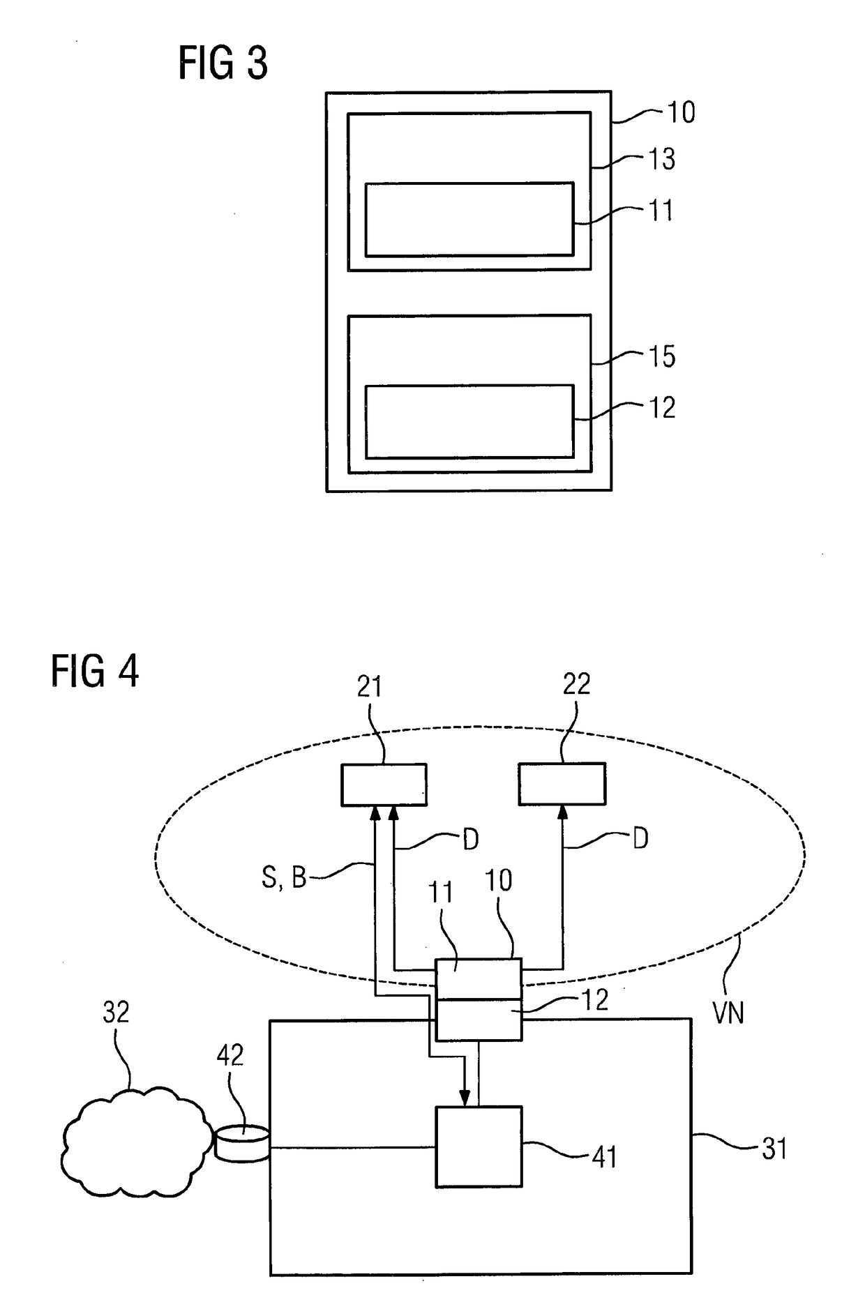
[0039]FIG. 1 depicts a schematic block diagram of an embodiment of a device 10 for coupling a plurality of user entities 21, 22 in a communication network 31, 32.

[0040]FIG. 1 depicts two user entities 21 and 22, but more may be provided. The communication network 31, 32 includes a core mobile network 31 and at least one wireless mobile network. The communication network 31, 32 may include an Internet-Service-Provider network 32.

[0041]The device 10 in FIG. 1 includes a first unit 11 and a second unit 12. The first unit 11 is configured to provide communication links between each of the user entities 21, 22 and the core mobile network 31 of the communication network 31, 32.

[0042]The second unit 12 is configured to provide a number of virtual networks VN. FIG. 1 depicts one virtual network VN, but more virtual networks may be provided. The virtual network VN is configured to connect the user entities 21, 22 such that a direct communication D between the connected user entities 21, 22 i...


PUM


Abstract

Systems and Methods are provided for coupling a plurality of user entities in a communication network. A device includes a first unit for providing communication links between each of the user entities and a core mobile network of the communication network, and a second unit for providing a number of virtual networks. Each of the provided virtual networks is configured to connect at least two of the user entities such that a direct communication between the connected at least two user entities is provided.

Description

CROSS REFERENCE TO RELATED APPLICATION[0001]The present patent document is a § 371 nationalization of PCT Application Ser. No. PCT / EP2015 / 050675, filed Jan. 15, 2015, designating the United States, which is hereby incorporated by reference.FIELD[0002]Embodiments relate to a device for coupling a plurality of user entities in a communication network, a method, and a computer program product for coupling a plurality of user entities in a communication network.BACKGROUND[0003]Automation applications require, for example, a certain quality of service (QoS). When automation is realized via 4G cellular networks, data communication between automation devices, for example, between cranes and remote controls for the cranes, is required. Conventional deployments foresee that the data communication between the automation devices traverses the core mobile network of the 4G operators. By traversing the core mobile network, additional latencies and jitter may be induced. Also, more nodes are tran...

Claims


Application Information

Patent Timeline
15 Nov 2018
Publication
US20180332642A1
IPC
H04W76/14; H04W8/08
CPC
H04W76/14; H04W8/082; H04W8/08; H04W76/10
Inventors
SCHEFFEL, MATTHIAS; WALEWSKI, JOACHIM