IC card terminal

a terminal and card reader technology, applied in the field of card reader terminals, can solve problems such as communication errors, application errors, and extreme troubl

Inactive Publication Date: 2005-03-15
FUJITSU LTD
View PDF14 Cites 8 Cited by
  • Summary
  • Abstract
  • Description
  • Claims
  • Application Information

AI Technical Summary

Benefits of technology

An object of the present invention is to provide an IC card terminal that can execute communication process

Problems solved by technology

However, when terminal applications and card applications have one-to-many relationships as described above, to add card applications corresponding to new functions to an IC card or to change some functions, all of the terminal applications of an IC card terminal must be newly created and exchanged, which is extremely troubleso

Method used


Image

  • IC card terminal
  • IC card terminal
  • IC card terminal

Examples


Embodiment Construction

An embodiment of the present invention is described below according to the figures. However, the technical range of the present invention is not limited to the embodiment presented.

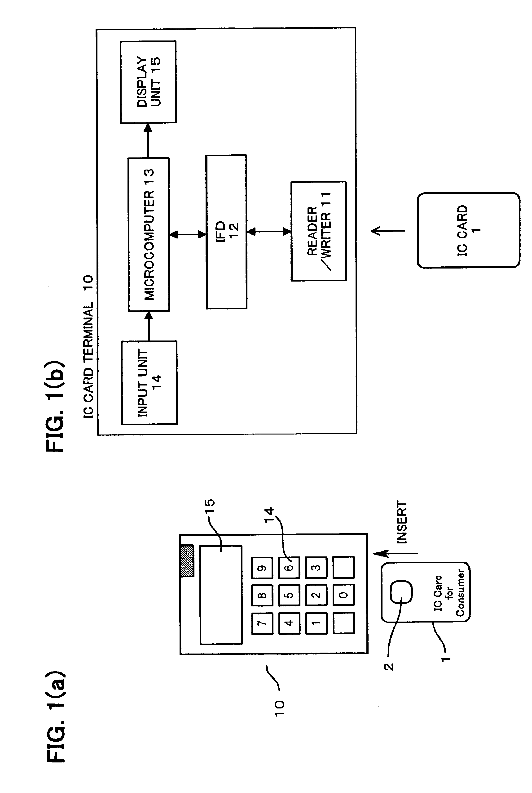
FIG. 1 is a schematic diagram of an IC card terminal in an embodiment of the present invention. FIG. 1(a) is an external view, and FIG. 1(b) is a block diagram. IC card 1 contains built-in LSI chip 2, which supports a plurality of functions such as credit card or electronic money functions. LSI chip 2 stores card applications corresponding to each of the functions. IC card terminal 10, which is a handy-type terminal as shown in FIG. 1(a), for example, comprises an input unit 14 for entering information such as an amount of money or password, a display unit 15 using liquid crystal or the like, and an IC card insertion slot, which is not illustrated. In addition, IC card terminal 10 has a built-in reader / writer 11 for reading data from and writing data to IC card 1, an IFD (interface device) 12 for controll...


PUM


Abstract

A communication control function for prohibiting communication with card programs due to other terminal applications while a certain terminal application is communicating with its corresponding card program is assigned by the present invention to the IFD driver, which controls communication with an IC card, in an IC card terminal. This enables an IC card terminal to process commands from a plurality of terminal applications without causing an error to occur.

Description

TECHNICAL FIELDThe present invention relates to an IC card terminal for accessing an IC card and executing IC card functions.BACKGROUND ARTAn IC card is a plastic card containing an embedded LSI chip with on-chip CPU and memory. Since an IC card can ensure higher security and store a greater volume of data than a conventional magnetic card, a single card can be used to implement a plurality of functions such as credit card or electronic money functions. A variety of IC card standards are well known such as MULTOS, JAVACARD, and Smart Card for Windows. Various types of IC card terminals have been provided for accessing and communicating with these kinds of IC cards.FIG. 4 is a diagram showing a first example of the configuration of communication between an IC card and IC card terminal by using the conventional method. FIG. 4 shows the program structures of the IC card and IC card terminal, respectively, and the inter-program communication configuration. IC card 1 is equipped with car...

Claims


Application Information

Patent Timeline
IPC IPC(8): G07F7/10G06K7/00
CPCG06K7/0008G07F7/1008G06Q20/40975G06Q20/341
Inventor HOSOGOE, TAKASHIHYODO, YOSHIIYAMATE, YASUMASA
Owner FUJITSU LTD
Why Eureka
Try Eureka