Perpetual magnetoelectric energy direct current power supply

a magnetoelectric energy and direct current technology, applied in the field of magnetoelectricity, can solve problems such as the disassembly or removal of the direct power source, and achieve the effect of optimizing the efficiency of electric transfer

US20180337617A1Inactive Publication Date: 2018-11-22GULLIVER KENNETH A
3 Cites 2 Cited by

Patent Information

Authority / Receiving Office
US · United States
Current Assignee / Owner
Publication Date
2018-11-22
Estimated Expiration
Not applicable · inactive patent

Smart Images

  • Figure 1
    Figure 1
  • Figure 2
    Figure 2
  • Figure 3
    Figure 3
Patent Text Reader

Abstract

The system provides for the transformation of permanent magnetic energy into a continuous electric energy current flow within a circuit. This is accomplished by creating a very strong egg shaped planetary permanent magnet. The magnet contains a longitudinal channel through its center to allow for initial energization. The initial energization is accomplished by applying a very strong burst of electrical current from a direct current power source. The magnet embodying the present invention is an egg shaped object that shall be held in one place without any physical or visible rotation of the magnet itself. Instead, the egg shape of the magnet creates varying field strengths patterns for energy transfer and polarization due to the internal left hand rule principles of electric current. This arrangement will create a permanent or near permanent perpetuating magnetic field. This magnetic field maintains intrinsic, centripetal, magnetic forces that create a magnetic whirl-pool that rotates the magnetic field within the magnet without rotating the magnet itself. The system created by the present invention is capable of self-sufficiency, recharging itself through power flow in the system's circuit. Additionally, the power is supplemented with atmospheric energy seeking termination, or moving towards the magnet, due to the centripetal forces generated by the magnetic angular momentum depression inside the magnet.
Need to check novelty before this filing date? Find Prior Art

Description

FIELD OF THE INVENTION

[0001] The present invention relates to the field of magneto-electricity, in particular, to a method of supplying energy through the use of magnets and a device applying said method.BACKGROUND OF THE INVENTION

[0002] Artificial source of power has been the driving force behind everything made by humans and has been the one single element that propelled humanity from the dark ages into modern times. The term “artificial” in this context denotes mechanical power derived from fuel, with one such fuel being electricity. However, as with all fuels, the production of electricity requires an investment of considerable production costs.

[0003] Electricity is perceived as the ideal fuel of the future. Since its discovery some 150 years ago, electricity generation and usage has become an increasingly sophisticated and efficient process. For example, over the last several years, while the use of electrical machinery has been increasing, as it has been ever since electricity wa...

Examples

Embodiment Construction

[0018]The preferred embodiments of the present invention will now be described with reference to the drawings. Identical elements in the various figures are identified with the same reference numerals.

[0019]Reference will now be made in detail to embodiment of the present invention. Such embodiments are provided by way of explanation of the present invention, which is not intended to be limited thereto. In fact, those of ordinary skill in the art may appreciate upon reading the present specification and viewing the present drawings that various modifications and variations can be made thereto.

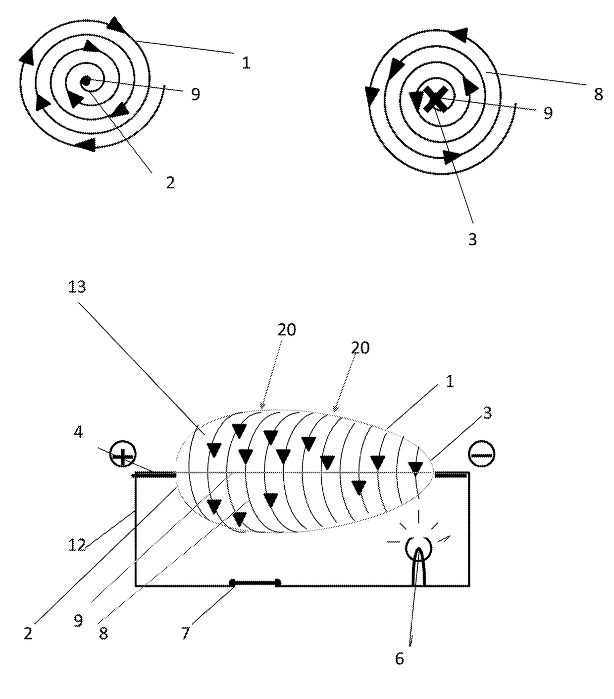
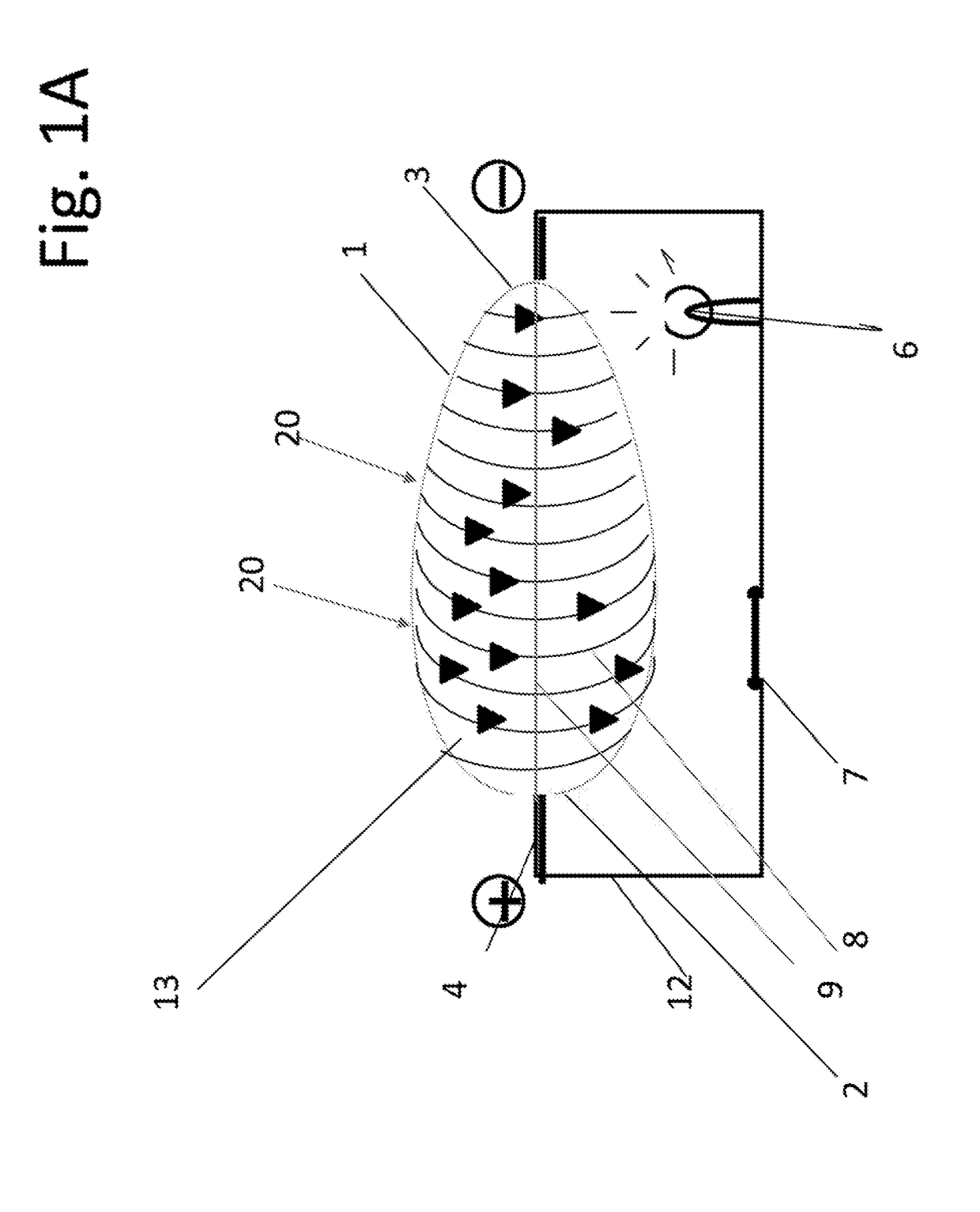
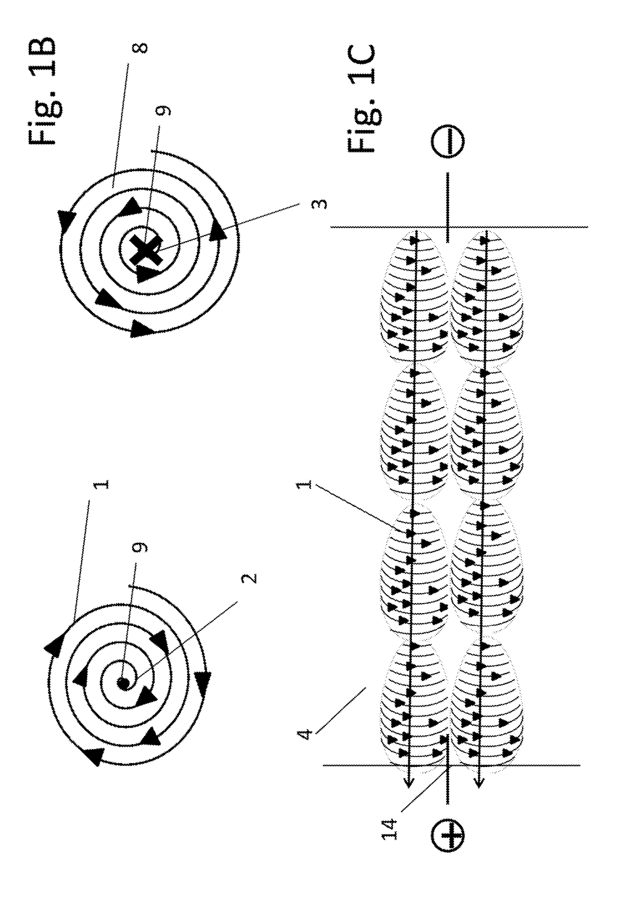
[0020]Turning now descriptively to the drawings, in which similar reference characters denote similar elements throughout the several views, the figures illustrate a perpetual or nearly perpetual permanent magnetic energy system showing in the FIG. 1A the magnet 1, the longitudinal channel 9, the forward section 3, the rear section 2, the magnetic field 8, the wire 4, the load 6, the switch 7, ...