Wide field personal display device

a display device and wide field technology, applied in the field of personal display devices, can solve the problems of inability conventional design approaches that have proved difficult to scale to meet the demands of size, weight and placement, and poorly address optical problems, so as to improve the field of view, reduce image aberration, and large pupil size

Active Publication Date: 2019-02-28
CORNING INC
View PDF5 Cites 3 Cited by
  • Summary
  • Abstract
  • Description
  • Claims
  • Application Information

AI Technical Summary

Benefits of technology

[0051]The display apparatus designs described herein result in increased field of view, reduced image aberration, and large pupil size at low cost compared to other designs, thereby providing personal display device designs that are readily manufacturable and inherently adapted to the human visual system. Additional features and advantages will be set forth in the detailed description which follows, and in part will be readily apparent to those skilled in the art from the description or recognized by practicing the embodiments as described in the written description and claims hereof, as well as the appended drawings.

Problems solved by technology

In particular, imaging optics that present the electronically processed images to the viewer have been disappointing.
Conventional design approaches have proved difficult to scale to the demanding size, weight, and placement requirements, often poorly addressing optical problems related to field of view and distortion, eye relief, pupil size, and other factors.

Method used


Image

  • Wide field personal display device
  • Wide field personal display device
  • Wide field personal display device

Examples


Embodiment Construction

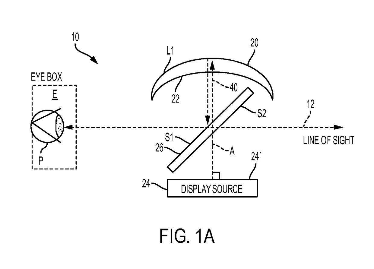
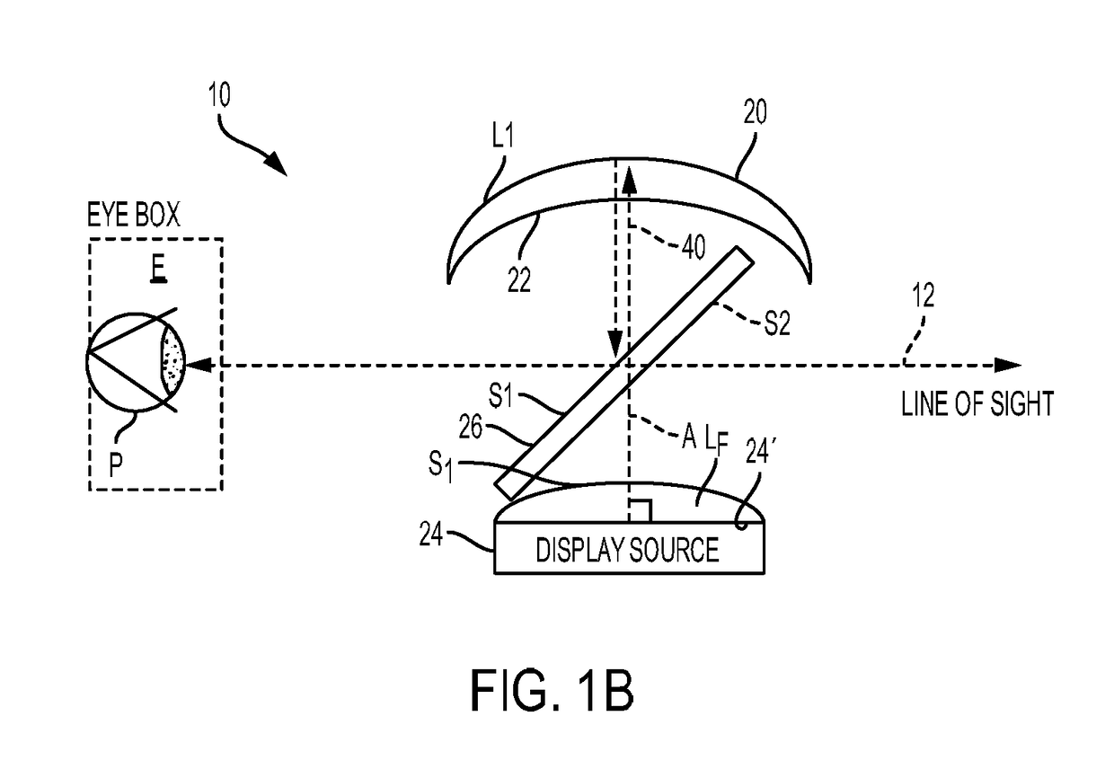
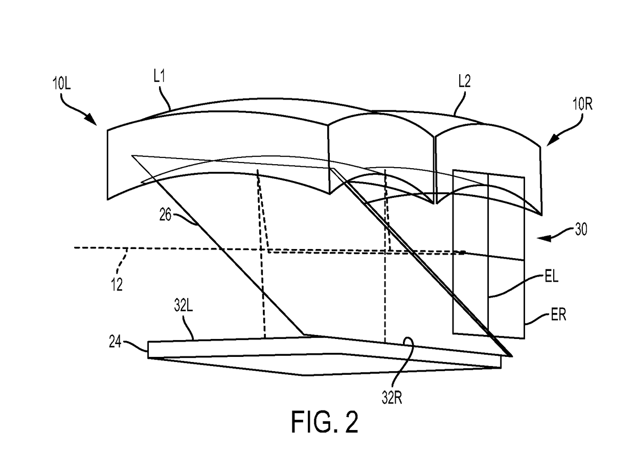
[0073]Figures shown and described herein are provided in order to illustrate key principles of operation and fabrication for an optical apparatus according to various embodiments and a number of these figures are not drawn with intent to show actual size or scale. Some exaggeration may be necessary in order to emphasize basic structural relationships or principles of operation.

[0074]The figures provided may not show various supporting components, including optical mounts, power sources, image data sources, and related mounting structure for standard features used in a display device. It can be appreciated by those skilled in the optical arts that embodiments of the present invention can use any of a number of types of standard mounts and support components, including those used with both wearable and hand-held display apparatus.

[0075]In the context of the present disclosure, terms such as “top” and “bottom” or “above” and “below” or “beneath” are relative and do not indicate any nec...


PUM

PropertyMeasurementUnit
thicknessaaaaaaaaaa
focal lengthaaaaaaaaaa

Abstract

A display apparatus has an image generator that generates image-bearing light from a surface and a lens spaced apart from the image generator and having an aspheric incident refractive surface concave to the image generator and having an aspheric reflective surface concave to the image generator, wherein a principal axis of the reflective surface is normal to the image generator. A beam splitter plate disposed in free space between the image generator and the lens has first and second parallel surfaces that are oblique to a line of sight of a viewer. The lens and the beam splitter plate define a viewer eye box for the image-bearing light along the line of sight of the viewer.

Description

[0001]This application claims the benefit of priority under 35 U.S.C. § 119 of U.S. Provisional Application Ser. No. 62 / 551,886, filed on Aug. 30, 2017, the content of which is relied upon and incorporated herein by reference in its entirety.FIELD OF THE INVENTION[0002]The disclosure relates generally to personal display devices and more particularly to apparatus and methods for a wide-field head-mounted or other single-viewer display having a pupil imaging system.BACKGROUND[0003]Personal display devices make it possible to provide image content to a viewer in applications where the use of conventional display screens would be an encumbrance. Head-mounted devices (HMDs), such as display goggles, are being considered as a useful type of wearable personal display device usable in a variety of fields, with applications ranging from military, medical, dental, industrial, and game presentation, among others. Stereoscopic imaging, with its enhanced spatial representation and improved pres...

Claims


Application Information

Patent Timeline
Patent Type & Authority Applications(United States)
IPC IPC(8): G02B27/01G02B1/11G02B3/04
CPCG02B2027/0123G02B27/0172G02B1/11G02B3/04G02B17/0856
Inventor COBB, JOSHUA MONROE
Owner CORNING INC
Why Eureka
Try Eureka