Light converting device having a wavelength converting layer with a hydrophobic nanostructure

a technology of hydrophobic nanostructure and light converting device, which is applied in the direction of solid-state devices, electric lighting sources, and light sources. it can solve the problems of adding cost and complexity to the product and the process, and the construction provides no solution to the above problem

Active Publication Date: 2019-03-21
SIGNIFY HLDG BV
View PDF2 Cites 0 Cited by
  • Summary
  • Abstract
  • Description
  • Claims
  • Application Information

AI Technical Summary

Benefits of technology

[0018]In at least one exemplary embodiment, the light converting device further comprises a protective coating applied on top of the hydrophobic nanostructure. In at least one exemplary embodiment, the protective coating is silicone or polyurethane. The protective coating is applied to prote

Problems solved by technology

However, different materials each have their own refractive index and the light converting device thus has to be tuned for differe

Method used


Image

  • Light converting device having a wavelength converting layer with a hydrophobic nanostructure
  • Light converting device having a wavelength converting layer with a hydrophobic nanostructure
  • Light converting device having a wavelength converting layer with a hydrophobic nanostructure

Examples


Embodiment Construction

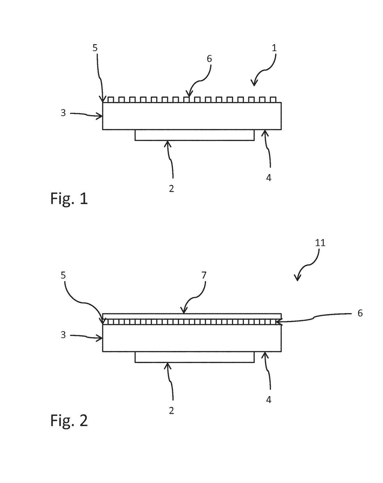
[0040]In the present detailed description, exemplary embodiments of a light converting device according to the present invention are mainly discussed with reference to schematic views showing a light converting device according to various embodiments of the invention. It should be noted that this by no means limits the scope of the invention, which is also applicable in other circumstances for instance with other types or variants of light converting device or components than the embodiments shown in the appended drawings. Further, that specific components are mentioned in connection to an embodiment of the invention does not mean that those components cannot be used to an advantage together with other embodiments of the invention. The invention will now be described with reference to the enclosed drawings where first attention will be drawn to the structure, and secondly to the function. Like reference characters refer to like elements throughout the description.

[0041]FIG. 1 shows ...


PUM


Abstract

The present invention relates to a light converting device (11) comprising a solid state light source (2) and a wavelength converting layer (3) arranged to at least partly wavelength convert the light emitted, in use, by the solid state light source (2), the wavelength converting layer (3) having a back side (4) facing the solid state light source (2) and a front side (5) opposite the back side (4), wherein the front side (5) of the wavelength converting layer (3) defines an exit window of the light converting device (11). The light converting device (11) further comprises a hydrophobic nanostructure (6) having spaced apart protrusions (66) arranged on the front side (5) of the wavelength converting layer (3) and a protective coating (7) applied on top of the hydrophobic nanostructure (6).

Description

FIELD OF THE INVENTION[0001]The present invention relates to a light converting device having a wavelength converting layer.BACKGROUND OF THE INVENTION[0002]Lighting devices based on solid state lighting technology which comprise a wavelength converting layer are known in the art, such lighting devices are referred to as light converting devices. The wavelength converting layer enables the use of more efficient light sources which, in use, do not emit light of a desired color. The wavelength converting layer converts the emitted light from the light source into the desired color. However, it is often required to protect the surface of the wavelength converting layer with a protective coating, and as the material of the protective coating has a different refracting index than the surrounding air, the spectrum of the light emitted from the light converting device is therefore altered due to refraction in the interface between the wavelength converting layer and the protective layer. T...

Claims


Application Information

Patent Timeline
IPC IPC(8): H05B33/14H01L33/50H01L33/54H01L33/56
CPCH05B33/14H01L33/504H01L33/505H01L33/508H01L33/54H01L33/56B82Y20/00B82Y30/00B82Y40/00H01L25/0753H01L33/44H01L33/501H01L2933/0025H01L2933/0041
Inventor SHOENMAEKERS, JORDY BERNARD MARGRETHBUKKEMS, PETER JOHANNES MARTINUS
Owner SIGNIFY HLDG BV
Why Eureka
Try Eureka