Method for attaching nut and collar to plate material and attachment structure of nut and collar to plate material

a technology of plate material and nut, which is applied in the field of automobiles, can solve the problems of deterioration in the workability of the attachment, thermal strain likely to occur in the plate material b>2/b, and thermal strain, so as to improve the attachment strength of the nut and the peeling strength

Active Publication Date: 2019-07-25
AOYAMA SEISAKUSHO CO LTD +1
View PDF0 Cites 0 Cited by
  • Summary
  • Abstract
  • Description
  • Claims
  • Application Information

AI Technical Summary

Benefits of technology

[0014]According to the present invention, firstly, the nut is caulked and fixed to the plate material using a dedicated die, and the protrusion at an end of the collar is press-fitted into the recessed groove formed on the opposite surface of the plate material at the time of the caulking fixation, thereby caulking and fixing the collar to the plate material. Therefore, welding is unnecessary, and there is no possibility of strain occurring in the plate material due to the welding heat, unlike in the prior art. Therefore, it is possible to correctly attach the nut to the plate material in a perpendicular direction. Moreover, unlike in the prior art, there is a great advantage of, for example, no possibility that the peeling strength and the idling torque of the nut may be deteriorated by the welding heat. Since welding is not performed, even when the plate material is made of aluminum, it is possible to attach the collar to the plate material. Furthermore, by attaching the collar, the attachment strength of the nut can be improved more than in the case of attaching the nut independently.

Problems solved by technology

However, with this structure, it is necessary to rotate the nut on the back surface of the plate material, which causes a problem of deterioration in attachment workability.
However, when welding is performed from both front and back surfaces at the same portion of the plate material 2 in this manner, thermal strain is likely to occur in the plate material 2 due to the thermal influence of welding.
However, when a collar 3 is welded to the back surface of the plate material 2, there is a possibility that thermal strain may occur in the plate material 2, and, additionally, that the metal having flown into the recess of the pierce nut may be softened by the heat when welding the collar 3, thereby causing reductions in peeling strength and idling torque of the pierce nut.
Further, when the plate material 2 is made of aluminum, there is also a problem that the collar 3 cannot be attached by welding.

Method used


Image

  • Method for attaching nut and collar to plate material and attachment structure of nut and collar to plate material
  • Method for attaching nut and collar to plate material and attachment structure of nut and collar to plate material

Examples


example

[0028]In order to confirm the effect of the present invention, the following test was conducted.

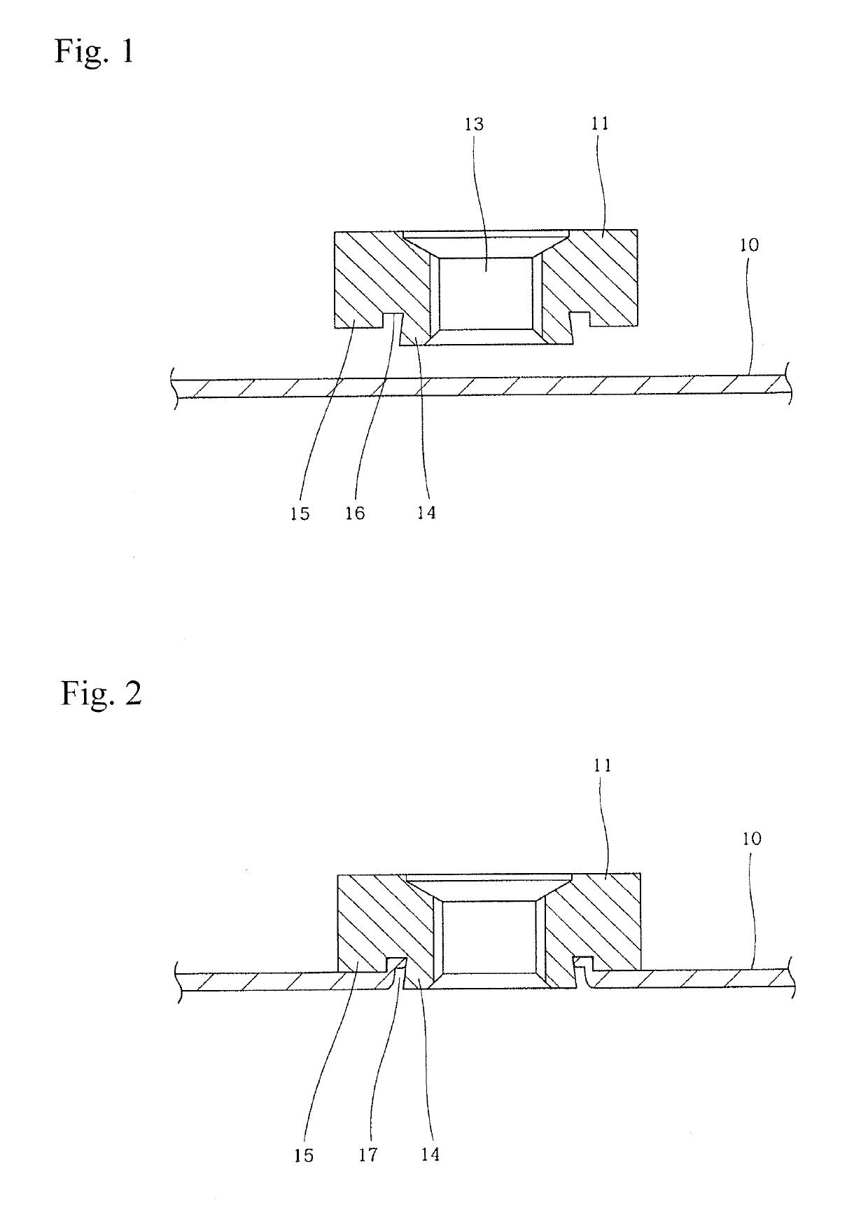
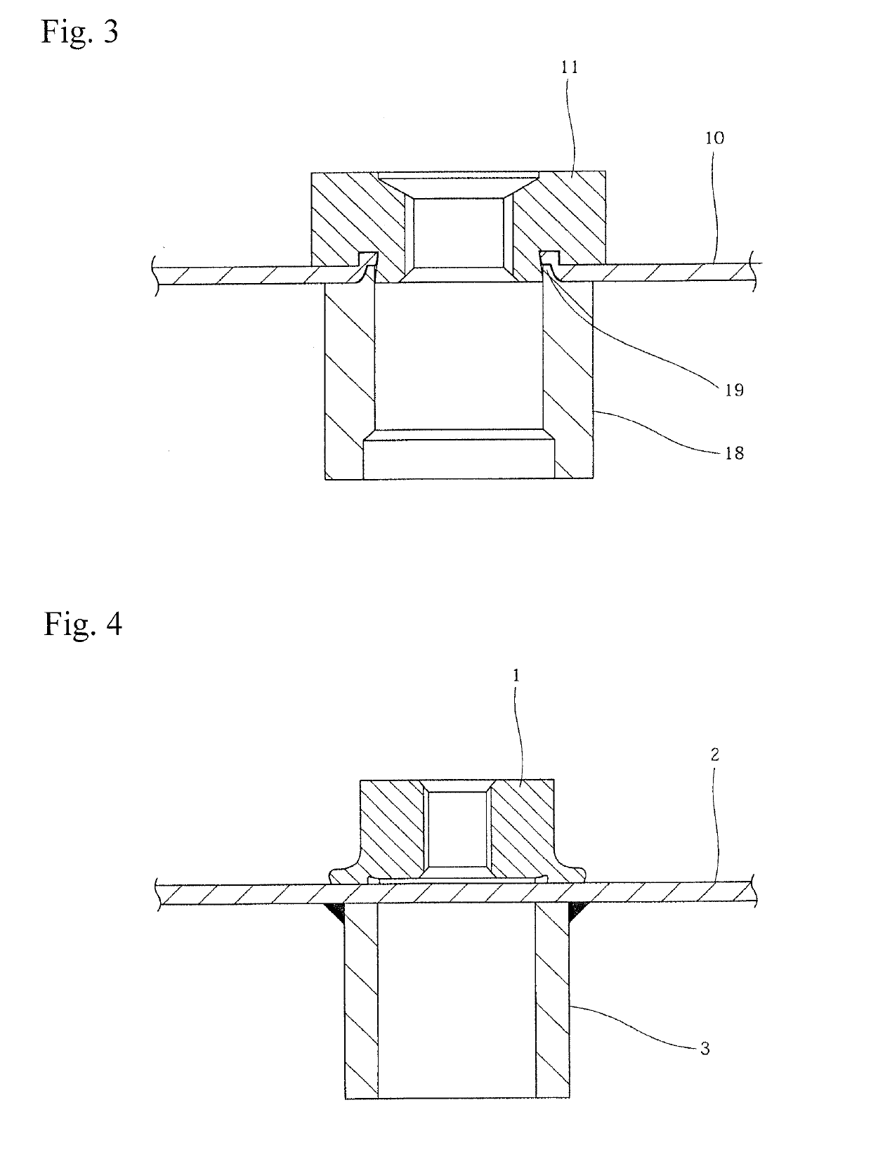
[0029]A pierce nut with a diameter of 22 mm was caulked to a panel made of a steel plate having a thickness of 1.2 mm by using a dedicated die. By this caulking, an annular recessed groove having an outer diameter of 14.6 mm and a width of 1 mm was formed on the opposite surface of the metal panel. Using this annular recessed groove, a collar having an outer diameter of 20 mm, an inner diameter of 12.5 mm, and a length of 15 mm was attached. The collar had an annular protrusion having an outer diameter of 14.6 mm and a width of 1 mm on one end face of the collar, and this annular protrusion was press-fitted into the annular recessed groove of the metal panel described above by using a pressing machine.

[0030]Next, drag torque of the pierce nut was measured. The measurement was carried out by a method of using a torque sensor for measuring the torque at which the pierce nut slipped away fro...


PUM


Abstract

A nut is caulked and fixed to a plate material and a protrusion at an end of a collar is press-fitted into a recessed groove generated on the opposite surface of the plate material at the time of the caulking fixation, thereby fixing the nut and the collar to both surfaces of the plate material, respectively. The plate material is, for example, a metal panel, and the nut is, for example, a pierce nut. Since the collar is caulked and fixed, thermal strain is not generated.

Description

[0001]This application claims the benefit under 35 USC § 119(a)-(d) of Japanese Application No. 2018-010389 filed Jan. 25, 2018, the entirety of which is incorporated herein by reference.FIELD OF THE INVENTION[0002]The present invention relates to a method for attaching a nut and a collar to a plate material and an attachment structure of a nut and a collar to a plate material.BACKGROUND OF THE INVENTION[0003]In the technical field of automobiles and the like, in many cases, another member is fixed by a bolt to a plate material such as a metal panel. For this purpose, a through hole is formed in the plate material, a through hole is formed also in the other member, and a bolt is inserted through these through holes to tighten the metal panel and the other member and fix with a nut. However, with this structure, it is necessary to rotate the nut on the back surface of the plate material, which causes a problem of deterioration in attachment workability.[0004]Therefore, in this techni...

Claims


Application Information

Patent Timeline
Patent Type & Authority Applications(United States)
IPC IPC(8): F16B11/00F16B37/06
CPCF16B11/006F16B37/068F16B37/062
Inventor FUJIMOTO, YUKINORIKOGA, KAZUHIROMASUI, KEIICHIROASAI, YUUSUKETANABE, MASATOSHINIINOMI, HIROTAKA
Owner AOYAMA SEISAKUSHO CO LTD
Why Eureka
Try Eureka