Cleaning head for a vacuum cleaner

a cleaning head and vacuum cleaner technology, applied in the direction of cleaning equipment, suction hoses, suction nozzles, etc., can solve the problems of affecting the cleaning experience of users, so as to improve the cleaning experience for users, increase the stability of the vacuum cleaner, and minimise the uncontrolled twisting movement of the cleaning

Active Publication Date: 2020-01-30
GREY TECHNOLOGY
View PDF0 Cites 3 Cited by
  • Summary
  • Abstract
  • Description
  • Claims
  • Application Information

AI Technical Summary

Benefits of technology

[0021]The present inventors seek to reduce or avoid the above-stated problems and thereby improve the cleaning experience for the user. In particular, the inventors seek to increase the stability of a vacuum cleaner during periods of non-use and to minimise the uncontrolled twisting movement of the cleaning head when it is lifted from the surface being cleaned.

Problems solved by technology

A steering joint is, however, often disadvantageous, particularly during periods of non-use of a stick vacuum cleaner (during which periods the body is not held by the user).
The vacuum cleaner is top heavy and relatively unstable in that position, and unless it is well balanced the steering joint will often permit the body to rotate relative to the cleaning head, and to slide across and down the wall.
The significant weight of the body can cause damage to the wall, to the vacuum cleaner, and also to furniture and other items which are impacted by the body as it falls towards the floor.
Most users will be aware of this problem and during long term storage will usually wedge the body so that it cannot easily slide across and down the wall.
However, such arrangements are often not available during short-term periods of non-use, for example whilst moving furniture or other items during a cleaning operation.
Other users may, however, lean the vacuum cleaner against a wall, and it is recognised that such usage will often result in the vacuum cleaner sliding across and down the wall with a significant possibility of damage.
The steering joint of the cleaning head of a cylinder vacuum cleaner presents similar problems in that the rigid tube and flexible tube are often leant against a wall during short-term periods of non-use.
Only the most diligent of users will typically use the clip element during short-term periods of non-use, however, and such an arrangement is not suitable for use with a stick vacuum cleaner.
The offset weight is not a significant concern whilst the vacuum cleaner is in use upon a floor or other substantially horizontal surface, but when the cleaning head is lifted from the surface the offset weight of the cleaning head typically causes the cleaning head to twist around the rotatable joint.
The uncontrolled twisting of the cleaning head can be awkward and cumbersome for the user, especially when cleaning areas such as stairs where the cleaning head is repeatedly and frequently lifted from the surface.

Method used


Image

  • Cleaning head for a vacuum cleaner
  • Cleaning head for a vacuum cleaner
  • Cleaning head for a vacuum cleaner

Examples


Embodiment Construction

[0042]The invention will now be described in more detail, by way of example, with reference to the accompanying drawings, in which:

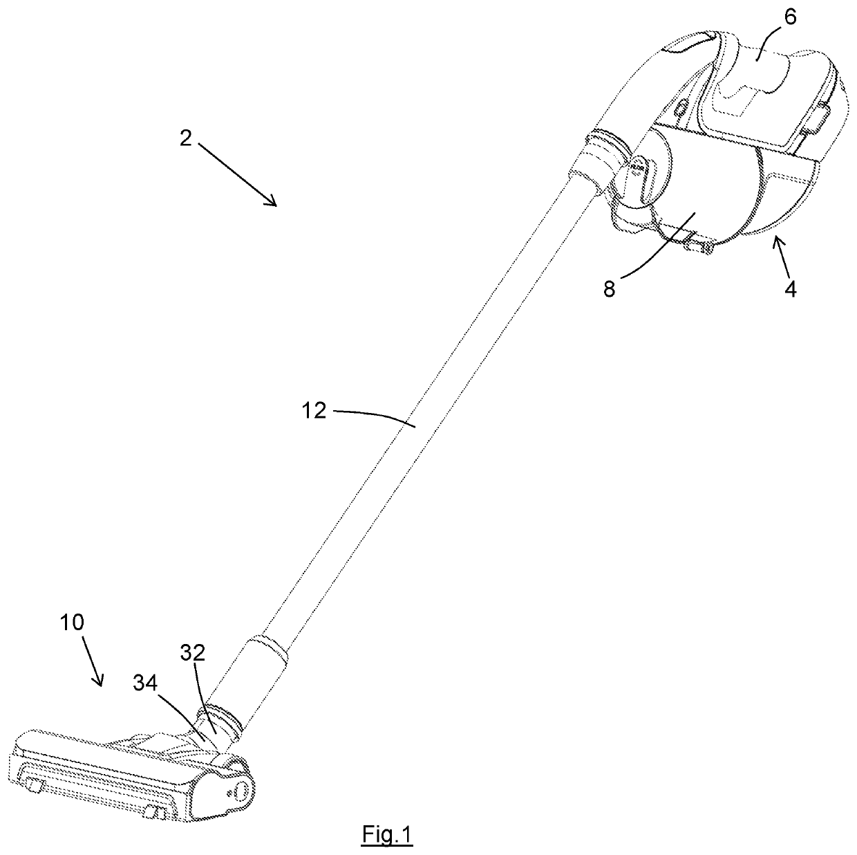
[0043]FIG. 1 shows a perspective view of a stick vacuum cleaner in a position of use, the stick vacuum cleaner having a cleaning head according to the present invention;

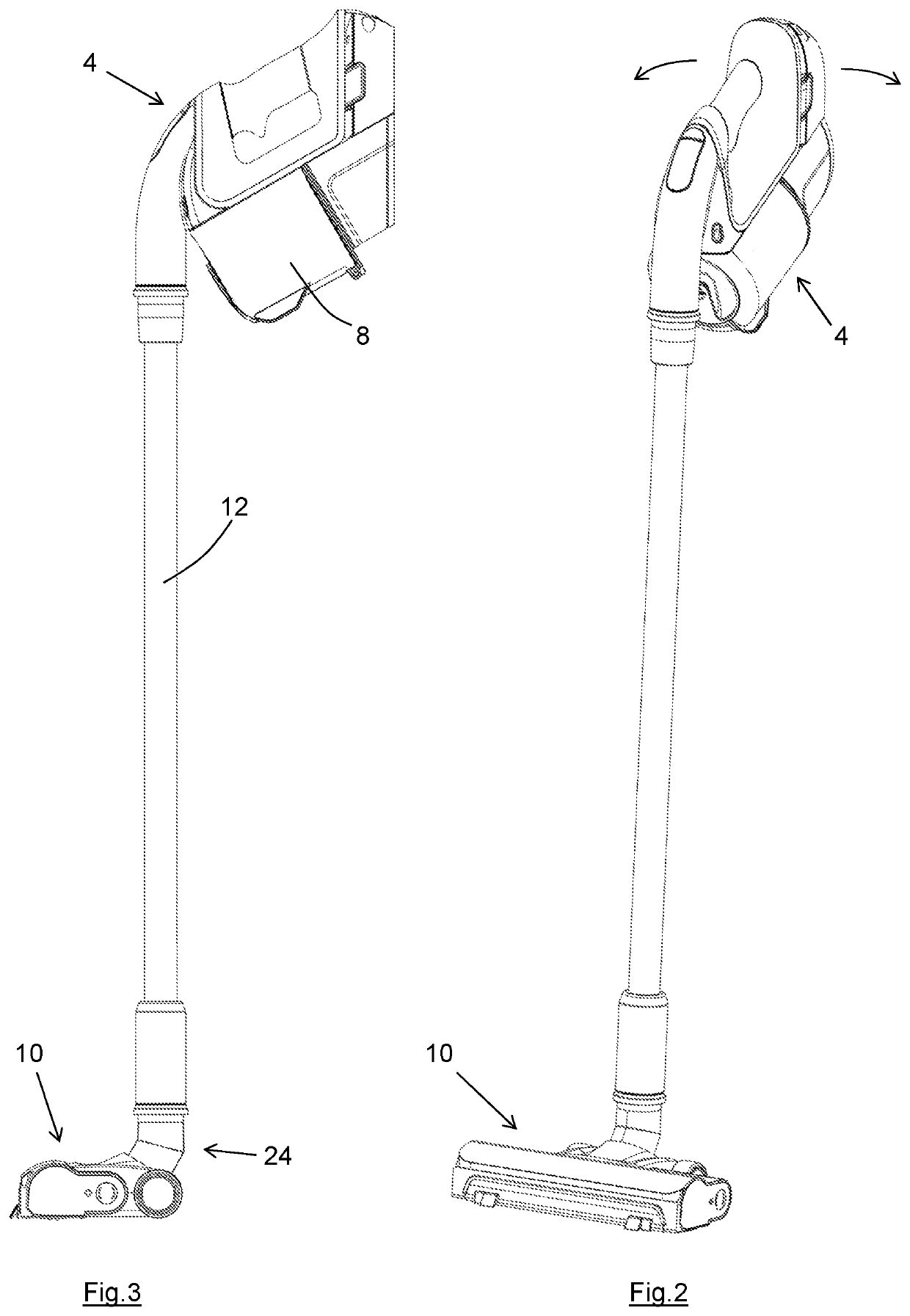
[0044]FIG. 2 shows a perspective view of the stick vacuum cleaner of FIG. 1 in a storage position;

[0045]FIG. 3 shows a side view of the stick vacuum cleaner in its storage position;

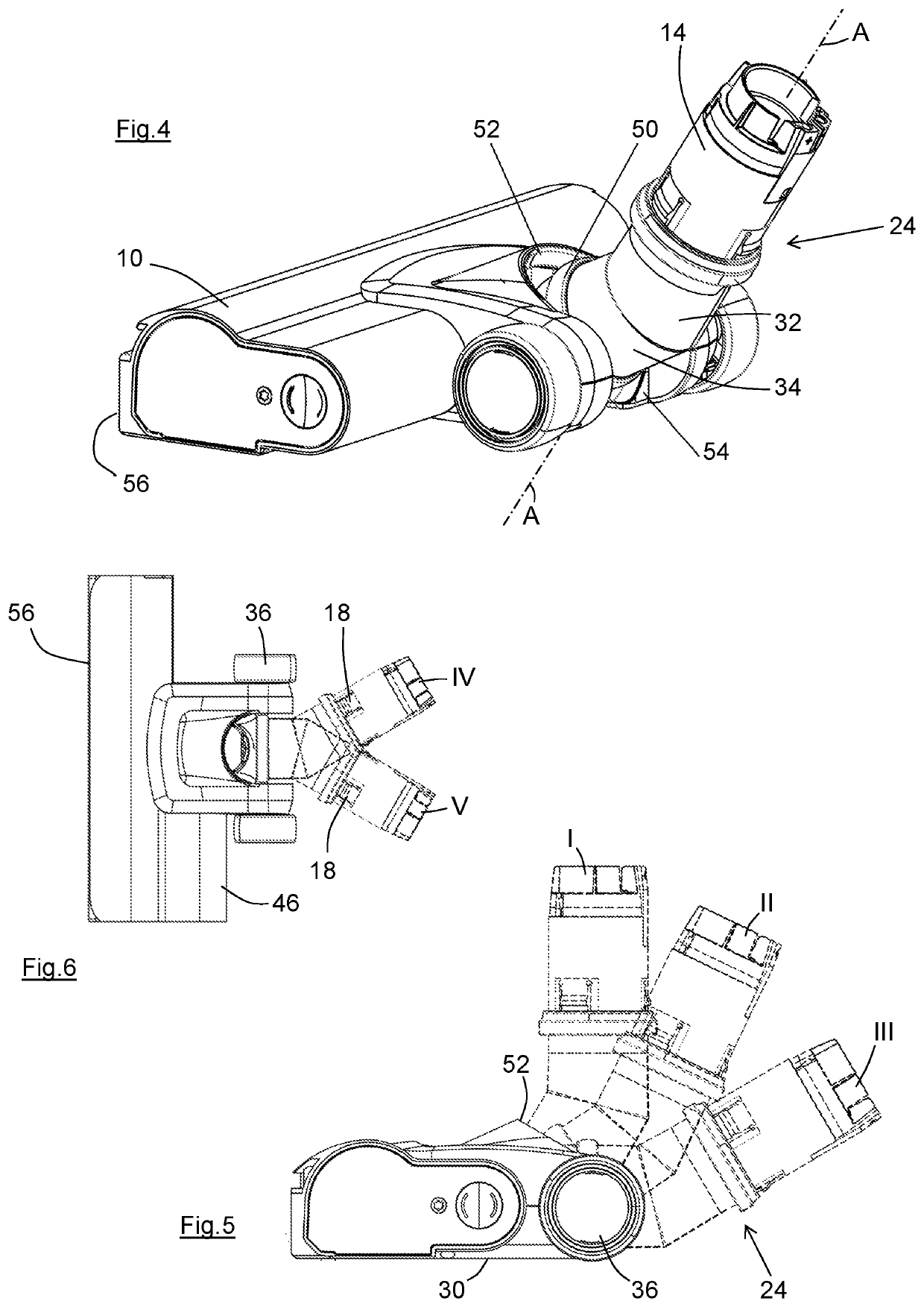
[0046]FIG. 4 shows a perspective view of the cleaning head of the stick vacuum cleaner of FIG. 1;

[0047]FIG. 5 shows a side view of the cleaning head of FIG. 4 with the rotatable section of the steering joint shown in dotted outline in three of its available pivoted positions relative to the cleaning head;

[0048]FIG. 6 shows a plan view of the cleaning head of FIG. 4 with the rotatable section shown in dotted outline in two of its available rotated positions relative to the cleaning head;

[0049]FIG. 7 shows a side...


PUM


Abstract

The invention relates to a cleaning head (sometimes called a “suction head”) for a vacuum cleaner, and in particular to a cleaning head having a motor to rotate a brush carried by the cleaning head. According to the invention there is provided a cleaning head (10) having a steering joint, the steering joint having a non-rotatable section (26) and a rotatable section (24) with a rotatable joint (20) between the non-rotatable section and the rotatable section. The cleaning head has a first holding region (52) which is engageable by a first part (50) of the rotatable section (24), the first holding region and the first part when engaged resisting rotation of the rotatable section. The cleaning head also has a second holding region (54) which is engageable by a second part (50) of the rotatable section (24), the second holding region and the second part when engaged resisting rotation of the rotatable section. The cleaning head can therefore be held against unwanted rotation in a storage position and also in a position in which it is suspended above a surface being cleaned.

Description

FIELD OF THE INVENTION[0001]The invention relates to a cleaning head (sometimes called a “suction head”) for a vacuum cleaner, and in particular to a cleaning head having a motor to rotate a brush carried by the cleaning head.[0002]In the following description, directional and orientational terms such as “upper”, “lower”, “top” etc. refer to the cleaning head in its normal orientation of use upon a substantially horizontal surface, as represented in FIG. 1 and others. It will be understood, however, that the cleaning head can be used in other orientations.BACKGROUND TO THE INVENTION[0003]Most vacuum cleaners are fitted with a cleaning head through which air and entrained dirt and debris pass on their way to a dirt collection chamber. The cleaning head has a sole plate adapted to overlie or engage a surface to be cleaned, the sole plate having an opening through which the air and entrained dirt can pass. The dirt collection chamber will typically contain a removable vessel, perhaps c...

Claims


Application Information

Patent Timeline
Patent Type & Authority Applications(United States)
IPC IPC(8): A47L9/04A47L5/24
CPCA47L9/0411A47L5/24A47L5/28A47L9/02A47L9/24A47L9/242
Inventor KNIGHT ADAMS, JACKEXLEY, ROSS
Owner GREY TECHNOLOGY
Why Eureka
Try Eureka