Double-roller floor sweeping equipment
A technology of equipment and cleaning rollers, which is applied in the direction of cleaning carpets, cleaning floors, cleaning equipment, etc., can solve the problems of easy entanglement of hair, incomplete cleaning, inconvenient cleaning of hair, etc., to achieve a balance between self-cleaning effect and self-cleaning resistance, and reduce time and distance, cleaning effect is better
- Summary
- Abstract
- Description
- Claims
- Application Information
AI Technical Summary
Problems solved by technology
Method used
Image
Examples
Embodiment 1
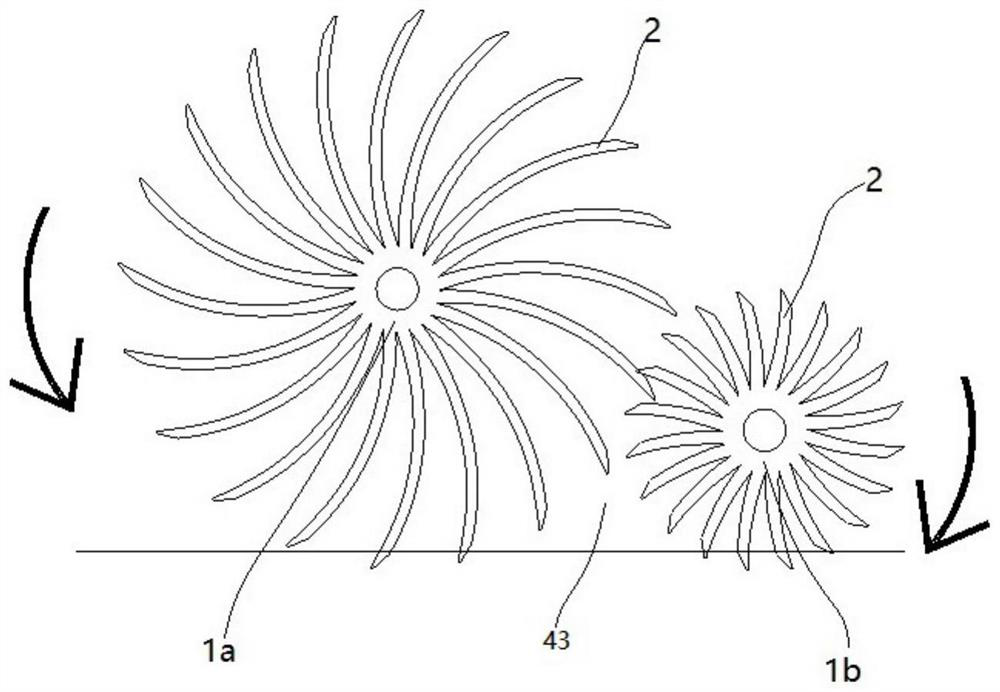
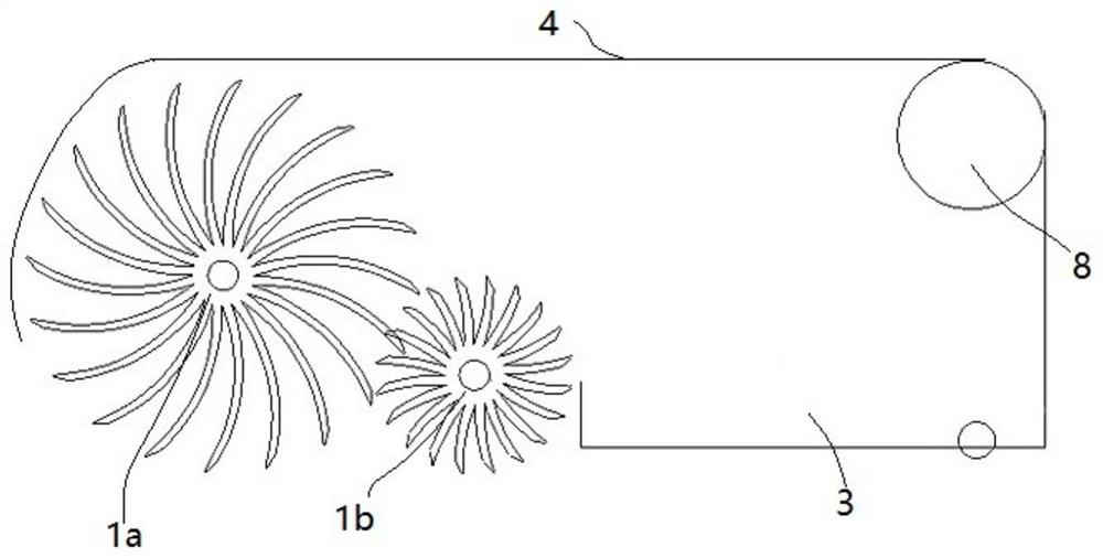
[0053] Example one, with figure 2 , including a cleaning component, and the cleaning component is installed in the front of the casing 4, the garbage bin 3 is located in the rear, the cleaning component includes two cleaning rollers 1, and the diameter of the front cleaning roller 1 is larger than the diameter of the rear cleaning roller 1, relying on the two A cleaning roller 1 picks up trash and dirty water.
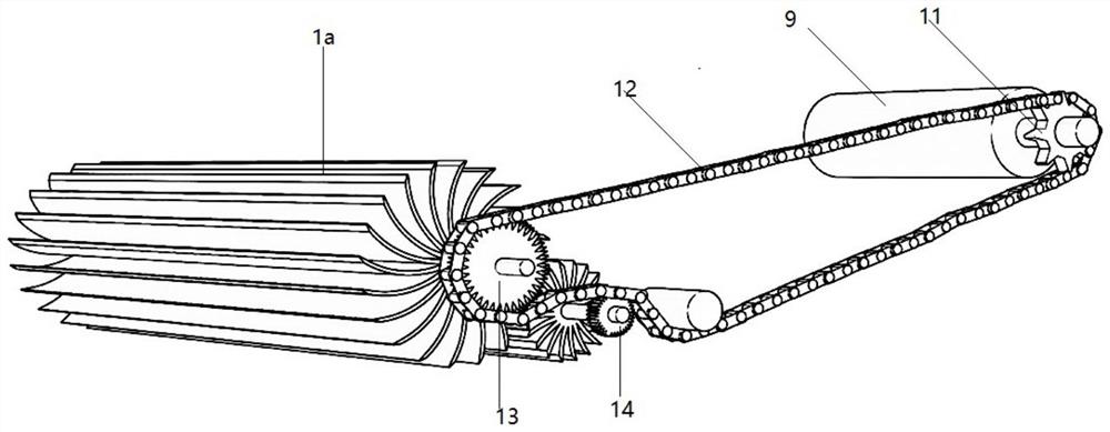
[0054] like image 3 As shown, the power and transmission unit includes a transmission device, a drive motor 9, and a battery. The transmission device includes a main sprocket 11 connected to the output end of the drive motor 9, a first sprocket 13 connected to the end of the large cleaning roller 1a, and a small cleaning roller 1a. The end of the roller 1b is fitted with a second sprocket 14, the main sprocket 11 is driven by the chain 12 with the first sprocket 13 and the second sprocket 14, and the large cleaning roller 1a and the small cleaning roller 1b rotate i...
Embodiment 2
[0062] Example 2, attached Figure 10 , which is different from the door 26 structure in the embodiment, the garbage bin 3 in this embodiment can also be a drawer 29 structure, and the drawer 29-type garbage bin 3 is slidably connected to the cabinet 4. When the garbage needs to be dumped, the drawer 29 is taken out and dumped That is, the primary filter screen 6 can be provided at the inner bottom of the drawer 29 to realize primary filtration. At the same time, it can be pushed out, and the drawer 29 is arranged on the right side of the garbage bin 3. Figure 11 , the structural setting of the drawer 29 needs to consider whether to install the power compartment 8, etc., and the space occupancy of the power compartment 8 needs to be avoided. At the same time, a silica gel column 30, etc. can be set on the drawer 29. The silica gel column 30 is fixed on the upper side of the drawer 29, located in The front side of the engine compartment 8 can intercept the garbage thrown to t...
Embodiment 3
[0063] Example 3, attached Figure 12 , on the basis of the first embodiment, considering improving the practicability of wiping and collecting water, the suction pump 17 can also be added to improve the water collection function, and the suction pump 17 is set and installed on the right side of the power cabin 8 (the suction pump 17 can also be It is a submersible pump structure, the water inlet end is directly installed in the water storage space 7), absorbs water from the water storage space 7, adds a sewage tank 35, can collect and pump dirty water into the sewage tank 35, and the sewage tank 35 can be hung or plugged. On the joystick 38, the sewage tank 35 is connected with the water supply pipe 19 by plug connection. When there is a lot of water on the surface, the sewage tank 35 can be disassembled and quickly poured out after it is full. The water supply pipe 19 can be arranged from the inside of the joystick 38, protrudes from the side wall of the joystick 38, and is ...
PUM
 Abstract
Description
Claims
Application Information
 - R&D
- Intellectual Property
- Life Sciences
- Materials
- Tech Scout
- Unparalleled Data Quality
- Higher Quality Content
- 60% Fewer Hallucinations
Browse by: Latest US Patents, China's latest patents, Technical Efficacy Thesaurus, Application Domain, Technology Topic, Popular Technical Reports.
© 2025 PatSnap. All rights reserved.Legal|Privacy policy|Modern Slavery Act Transparency Statement|Sitemap|About US| Contact US: help@patsnap.com


