Method for measuring bandwidth of linear motor

a linear motor and bandwidth measurement technology, applied in the microelectromechanical field, can solve the problems of linear motor parameters changing and deviating, the inability to directly measure the dynamic displacement of the vibrator, and the difficulty of measuring the bandwidth of the linear motor

Active Publication Date: 2020-02-20
AAC TECH PTE LTD
View PDF0 Cites 0 Cited by
  • Summary
  • Abstract
  • Description
  • Claims
  • Application Information

AI Technical Summary

Benefits of technology

[0015]Specifically, in step S1, a preset frequency band to be measured is divided into N segments, and N is an integer greater than 1; and in each segment of the frequency band to be measured, the frequency starting point, the frequency ending point and the interval between adjacent frequency points of the excitation signal are set. Specifically, for example, the frequency band to be measured ranges from 100 Hz to 300 Hz, and the frequency band to be measured is firstly divided into 201 segments, each segment is 1 Hz and then measured in each 1 Hz band. The present invention adopts the method of segmentation measurement, which can prevent the linear motor from heating under a long-time vibration, which causes parameters of the linear motor to change and to deviate from the linear working area, so that the frequency response model of the linear motor is no longer a linear system, and thus the measurement of the bandwidth is affected.

Problems solved by technology

In actual operation, it is difficult to measure the bandwidth of the linear motor.
Firstly, the linear motor will heat under a long-time signal exciting, causing parameters of the linear motor to change and to deviate from a linear working area, so that a frequency response model of the linear motor is no longer a linear system.
Secondly, a vibrator is packaged in an outer housing of the linear motor so that a dynamic displacement of the vibrator cannot be directly measured.
Thirdly, a large amplitude non-resonant frequency signal excites the linear motor, and a displacement peak at an initial phase is likely to exceed an allowable ultimate displacement of the vibrator, and consequently, a steady state displacement peak of the corresponding frequency at a steady phase cannot be measured.

Method used


Image

  • Method for measuring bandwidth of linear motor
  • Method for measuring bandwidth of linear motor
  • Method for measuring bandwidth of linear motor

Examples


Embodiment Construction

[0009]Hereafter, the present disclosure will be further described with reference to the accompanying drawings and embodiment.

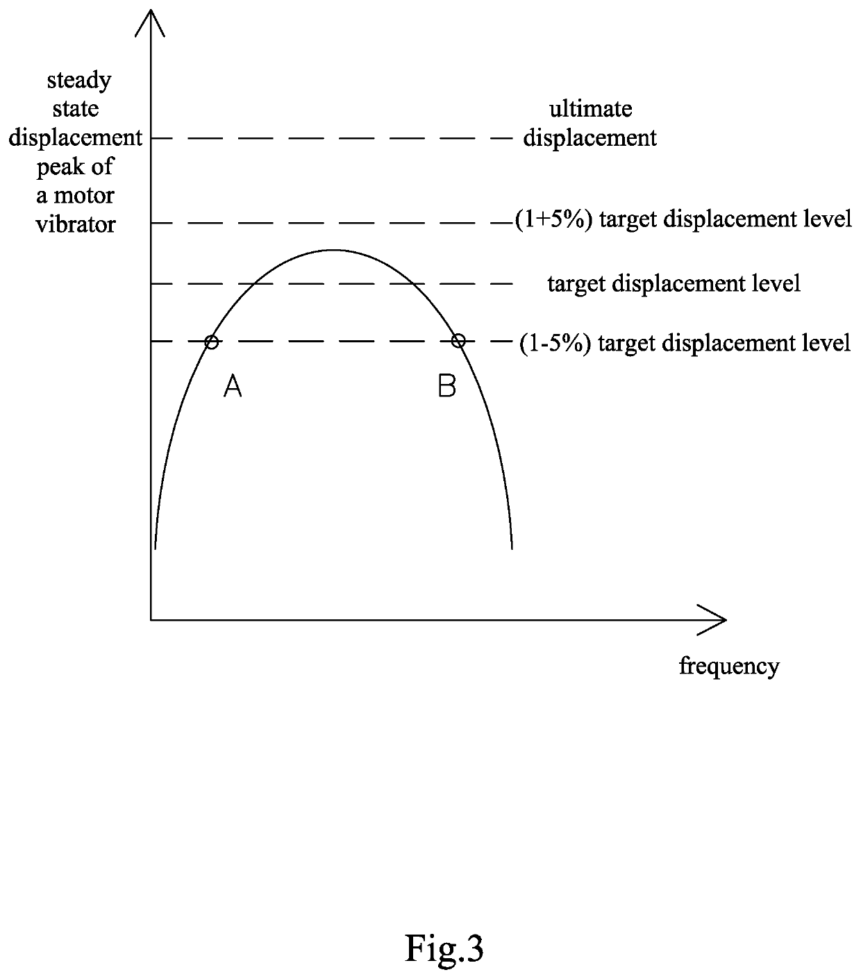
[0010]The method for measuring a bandwidth of a linear motor of the present embodiment is applied to linear motors equipped in the smart phones and the tablet computers, which can indirectly measure a dynamic displacement based on a calculation relationship between displacement and acceleration in a steady state vibration; and the method can measure the dynamic displacement corresponding to a large non-resonant frequency input signals by eliminating overshoot.

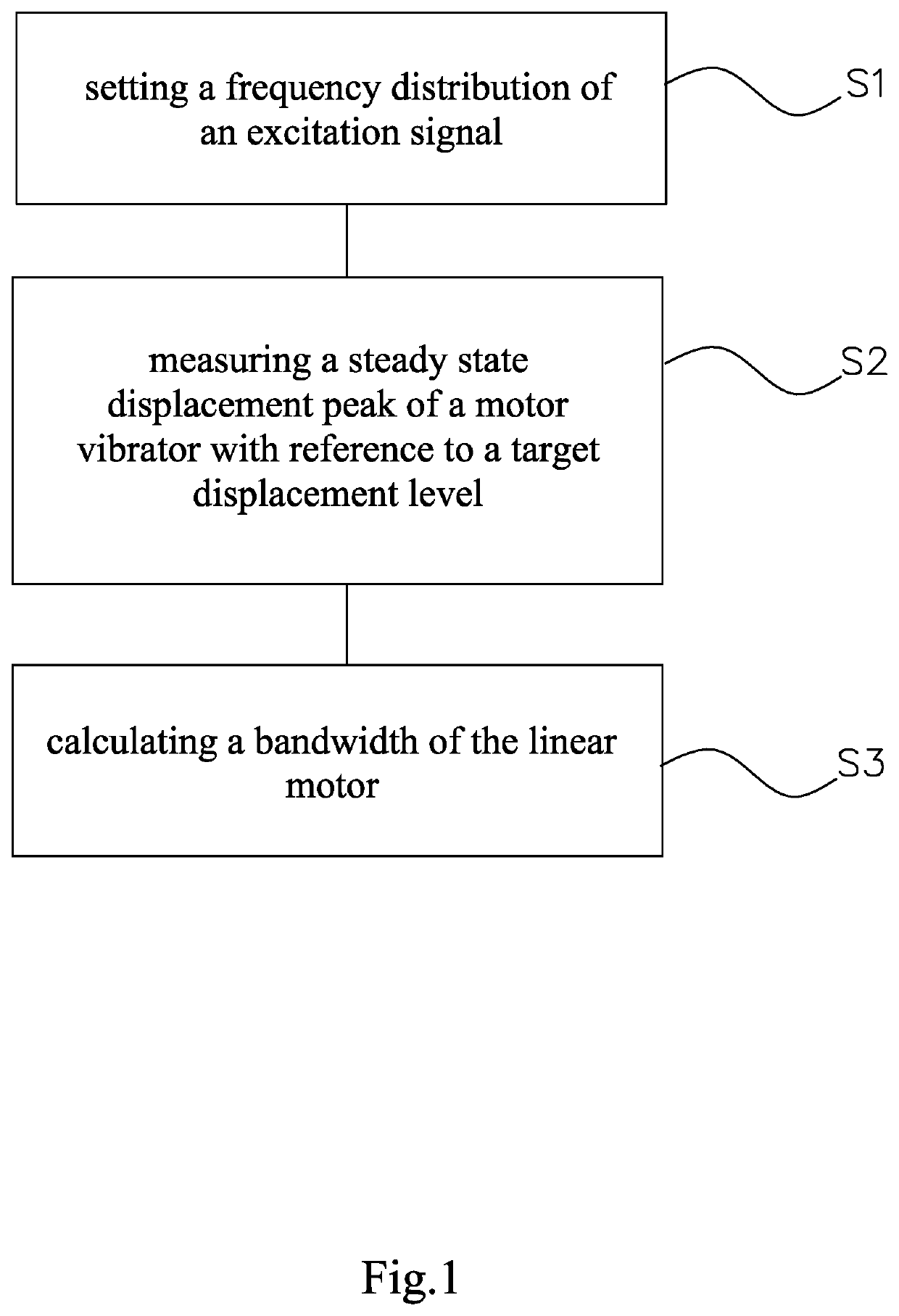
[0011]As shown in FIG. 1, the method for measuring the bandwidth of the linear motor of the present disclosure comprises the following steps:

[0012]step S1: a frequency distribution of an excitation signal is set, a frequency starting point, a frequency ending point, and an interval between two adjacent frequency points are determined, and a detailed list of measuring frequencies is provided;
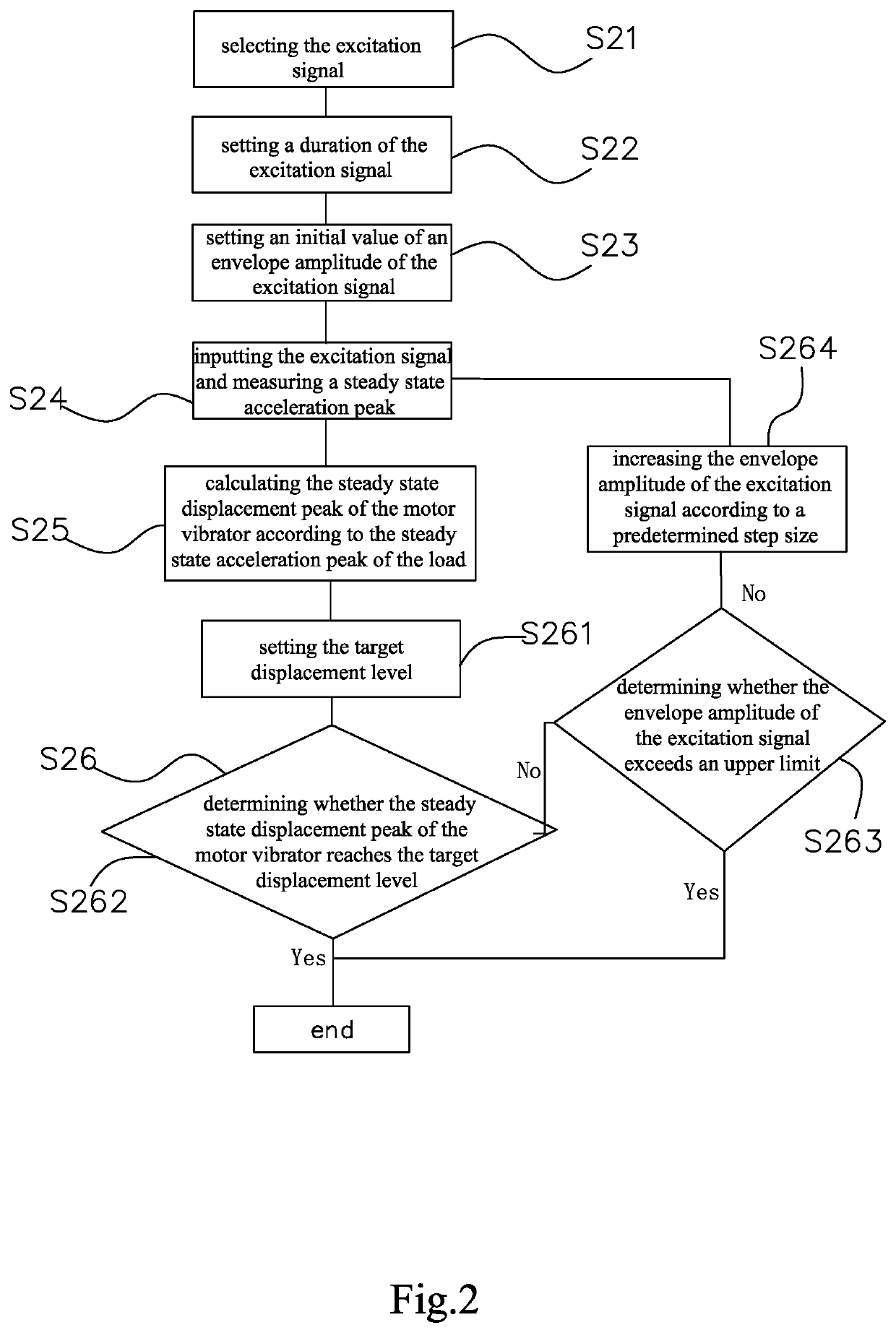
[0013]step S2:...


PUM


Abstract

The present disclosure provides a method for measuring bandwidth of linear motor, including the following steps: step S1: setting a frequency distribution of an excitation signal; step S2: with reference to a target displacement level, measuring a steady state displacement peak of a motor vibrator at each frequency point of the excitation signal, and obtaining a frequency response curve with reference to the target displacement level; step S3: according to the frequency response curve obtained in step S2, determining an upper frequency limit and a lower frequency limit with reference to the target displacement level, and obtaining a bandwidth of the linear motor by calculating a difference between the upper frequency limit and the lower frequency limit.

Description

FIELD OF THE PRESENT DISCLOSURE[0001]The present disclosure relates to microelectromechanical field, more particularly to a method for measuring a bandwidth of a linear motor.DESCRIPTION OF RELATED ART[0002]Taking electronic devices such as smart phones, tablet computers as carriers, a touch feedback function thereof brings users' a multi-level and a multi-dimensional touch interactive experience. Typical examples include: vibration experiences related to notices of short messages and incoming calls; time reminding vibration experiences initiated by alarm clocks and calendars; vibration experiences of low battery reminding; and vibration experiences related to movies and game plots.[0003]A linear motor is a core device which provides a touch feedback function. As the requirement for the touch effect design continuously increases, it is necessary to have a deeper and more accurate understanding of the performance of the linear motor itself. In many movies and games, according to need...

Claims


Application Information

Patent Timeline
Patent Type & Authority Applications(United States)
IPC IPC(8): G01R31/34H02P25/032
CPCH02P25/032G01R31/34G01R31/343
Inventor DENG, HANLINXIANG, ZHENGLU, XIANG
Owner AAC TECH PTE LTD
Why Eureka
Try Eureka