Stability of a resistance temperature detector

a temperature detector and stability technology, applied in the field of electric circuits, can solve the problems of affecting the stability or drift of a thin-film rtd, the type of rtd being prone to stress-induced resistance change, and the coils of the sensing element being susceptible, etc., to achieve the effect of improving the stability of the rtd

Active Publication Date: 2021-07-20
SENSATA TECHNOLOGIES INC
View PDF14 Cites 0 Cited by
  • Summary
  • Abstract
  • Description
  • Claims
  • Application Information

AI Technical Summary

Benefits of technology

[0007]One advantage of an RTD apparatus in which the voltage potential of the resistive meander is higher than the case of the RTD is that foreign matter having a positive charge will move away from the resistive meander and towards objects with a lower charge, such as the ground and the case of the RTD. As explained above, foreign matter may affect measurements of the voltage potential across the resistive meander, and thus the ability of the RTD to maintain the same resistance versus temperature relationship for the same conditions over time. Therefore, an apparatus that prevents foreign matter from contaminating the resistive meander of the RTD improves the stability of the RTD and is an advantage over the prior art.

Problems solved by technology

In the type of traditional RTD discussed above, the coils of the sensing element may be susceptible to shock or vibration, which may change the resistance of the coils by moving their positions relative to each other.
Coating this type of RTD with an insulating barrier, such as molten glass or ceramic cement, may reduce movement of the coils, but the differences in coefficients of thermal expansion may still result in this type of RTD being prone to stress induced resistance change.
However, the stability or drift of a thin-film RTD may be impacted by contamination of the resistive meander during production or use.
In this example, as the temperature changes, the resistance of the resistive meander would change by a different amount than the resistance of the foreign material, resulting in RTD drift.
However, in some RTD applications, this type of mechanical barrier may not sufficiently protect the resistive meander from contamination, resulting in some accumulation of foreign atoms on the resistive meander and an unacceptable change in the ability of the RTD to maintain the same resistance versus temperature relationship for the same conditions over time.

Method used


Image

  • Stability of a resistance temperature detector
  • Stability of a resistance temperature detector
  • Stability of a resistance temperature detector

Examples


Embodiment Construction

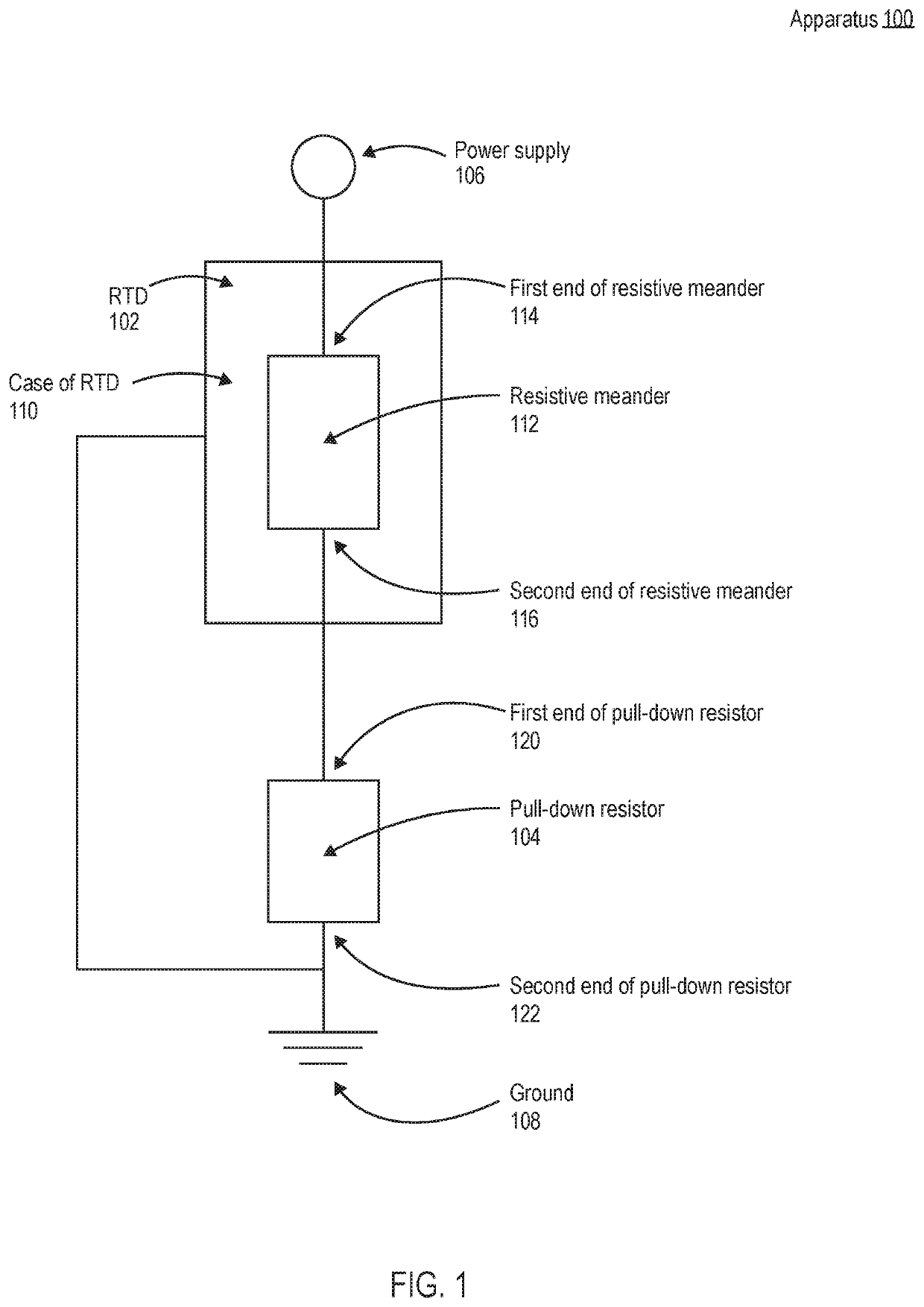
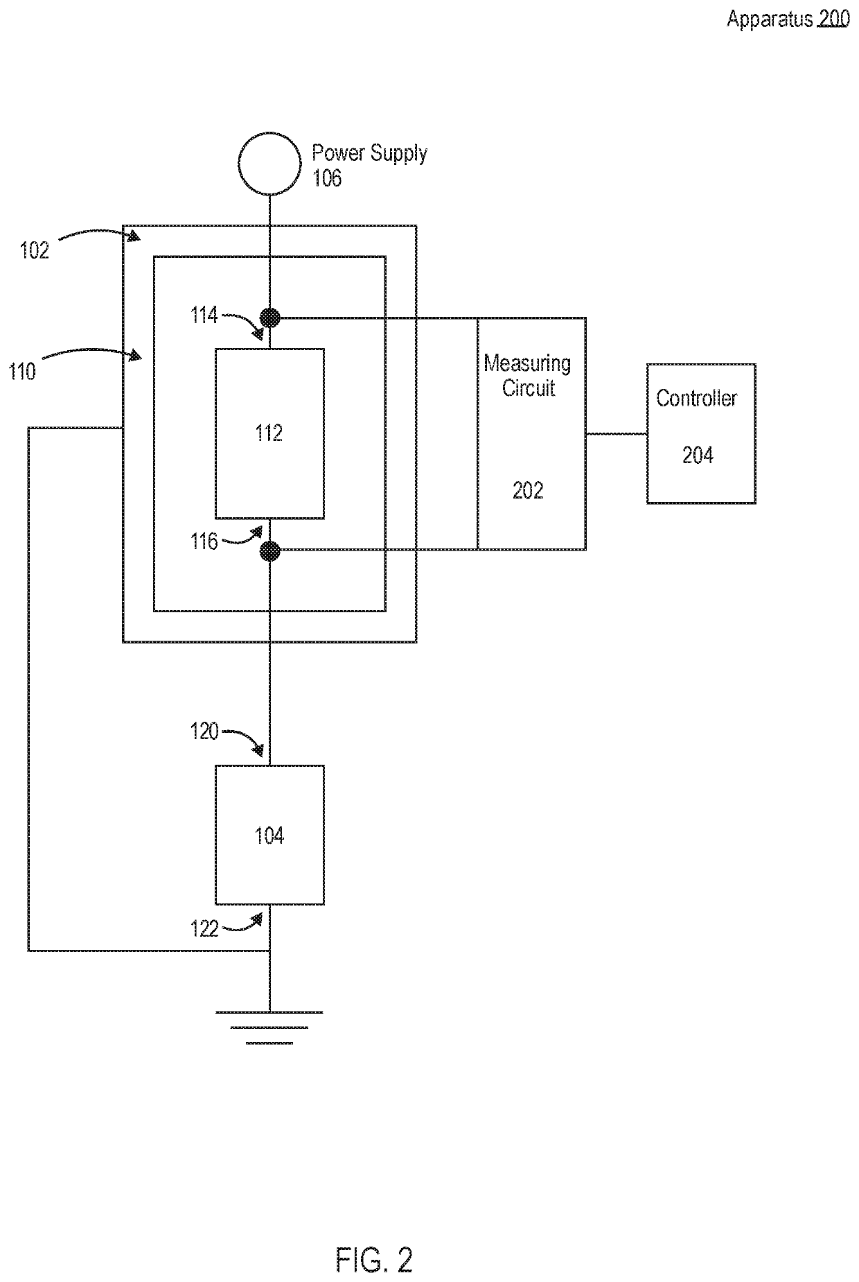
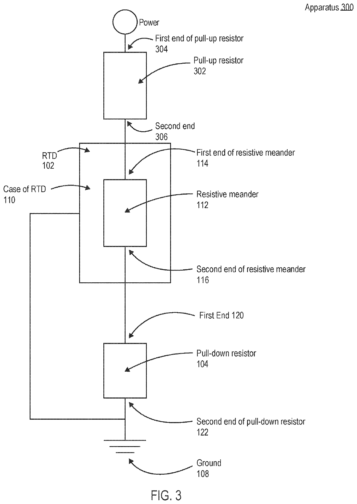
[0024]The present disclosure describes apparatuses and methods for improving the stability of a resistance temperature detector (RTD). As explained above, the stability or drift in the temperature resistance relationship of an RTD may be impacted by contamination of a resistive meander of the RTD during production or use of the RTD. Another common cause of drift is due to low resistance of the insulators. As will be described in detail below, according to embodiments of the present disclosure, an apparatus having an RTD may be configured with a pull-down resistor such that when power is provided to the apparatus, the voltage potential of the resistive meander is higher than the case of the RTD. Because the voltage potential of the RTD's resistive meander is higher than the case of the RTD, foreign matter having a positive charge (e.g., sodium ions) will move away from the resistive meander and towards objects with a lower charge, such as the ground and the case of the RTD. As explai...


PUM

PropertyMeasurementUnit
resistanceaaaaaaaaaa

Abstract

In a particular embodiment of the present disclosure, an apparatus is disclosed for improving for the stability of a resistance temperature detector (RTD). In this particular embodiment, the apparatus includes an RTD having a case surrounding a resistive meander deposited on a substrate. The RTD also includes a pull-down resistor. A first end of the resistive meander is configured for coupling to a positive power supply. The second end of the resistive meander is coupled to a first end of the pull-down resistor. The second end of the pull-down resistor is coupled to a ground. The case of the RTD is also coupled to the ground.

Description

FIELD OF THE INVENTION[0001]The present disclosure relates to electric circuits and more particularly to apparatuses and methods for improving the stability of a resistance temperature detector.BACKGROUND OF THE INVENTION[0002]A resistance temperature detector (RTD) (also known as resistance thermometer) is a passive circuit element whose resistance increases with increasing temperature in a predictable manner. The traditional RTD includes a non-conductive cylinder with a sensing element constructed of a conductive material, such as cooper or nickel wire, wrapped to form a precise resistance value. A measuring circuit may be connected to the wire to measure the change in the resistance of the sensing element by converting the resistance into a voltage.[0003]The reliability of an RTD to consistently provide accurate readings is a function of the RTD's ability to maintain the same resistance verses temperature relationship for the same conditions over time. The drift or change in the ...

Claims


Application Information

Patent Timeline
Patent Type & Authority Patents(United States)
IPC IPC(8): G01K7/16G01K1/00G01K15/00G01K7/18G01K1/08
CPCG01K7/183G01K1/08G01K7/16G01K7/206G01K1/10
Inventor CHEHLAROV, NIKOLAY S.
Owner SENSATA TECHNOLOGIES INC
Why Eureka
Try Eureka