Vehicle control apparatus

a technology of vehicle control and control apparatus, applied in the direction of brake systems, etc., can solve the problems of inability to accurately calculate the exact slip ratio, inability to properly control the braking force applied to the road wheels, and low speed of the second road wheel, so as to achieve the effect of reducing the braking for

Pending Publication Date: 2021-09-09
TOYOTA JIDOSHA KK
View PDF3 Cites 0 Cited by
  • Summary
  • Abstract
  • Description
  • Claims
  • Application Information

AI Technical Summary

Benefits of technology

[0007]The present disclosure has been made for solving the problems described above. An object of the present disclosure is to provide a vehicle control apparatus which can prevent all of the wheel speeds from simultaneously decreasing to the larger extent than the decrease of the actual vehicle body moving speed while a control to increase and decrease the braking forces applied to the road wheels, is executed.

Problems solved by technology

If the exact vehicle body moving speed cannot be calculated, the exact slip ratios cannot be calculated.
As a result, the braking forces applied to the road wheels cannot be properly controlled to prevent the slip ratios of the road wheels from significantly exceeding the optimum slip ratio.
Therefore, even when the speed of the first road wheel decreases, a possibility that the speed of the second road wheel decreases, is extremely low.
Therefore, even when the speed of the second road wheel decreases, a possibility that the speed of the first road wheel decreases, is extremely low.

Method used


Image

  • Vehicle control apparatus
  • Vehicle control apparatus
  • Vehicle control apparatus

Examples


Embodiment Construction

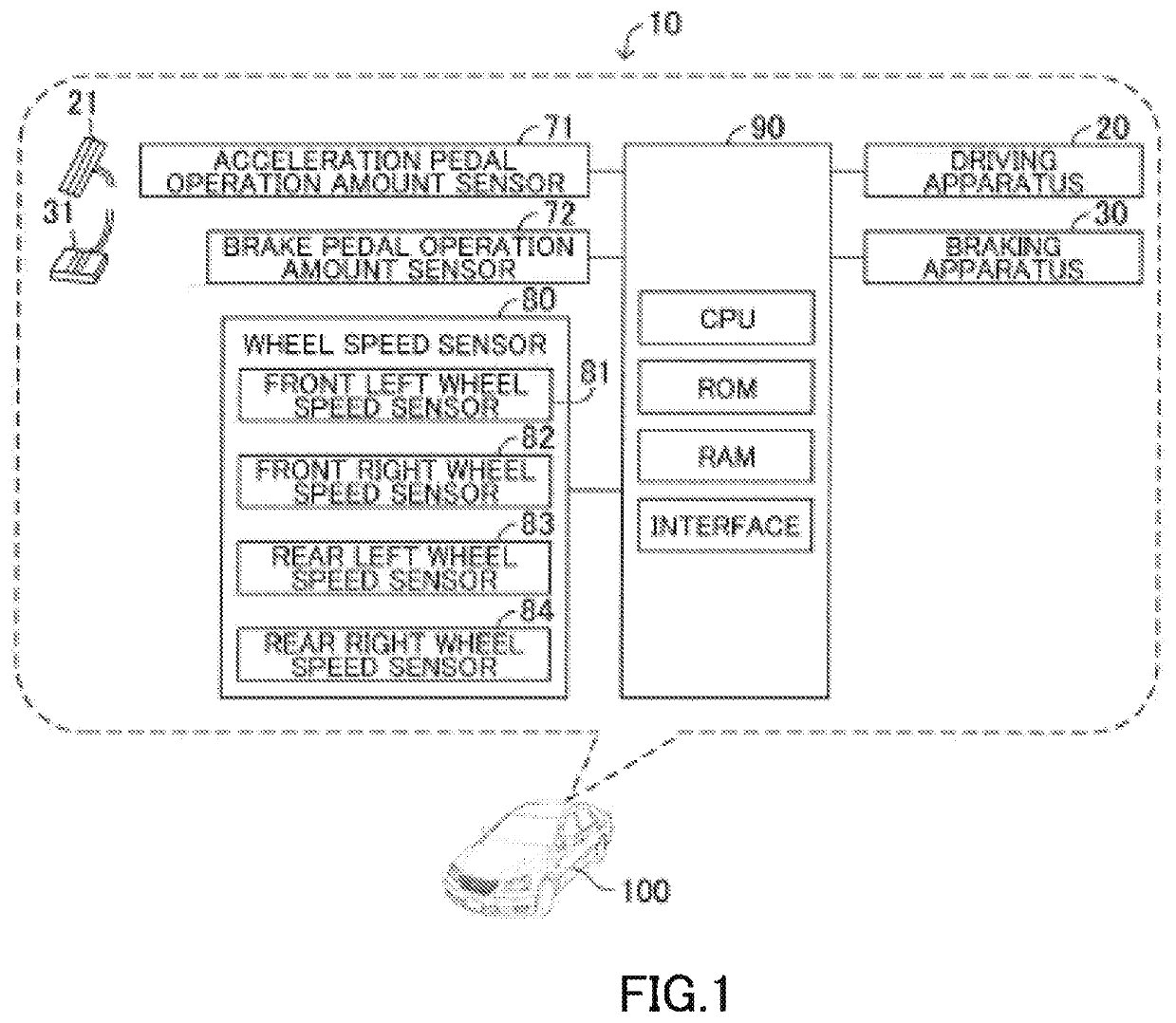
[0053]Below, a vehicle control apparatus 10 according to an embodiment of the present disclosure will be described with reference to the drawings. As shown in FIG. 1, the vehicle control apparatus 10 is installed on a vehicle 100.

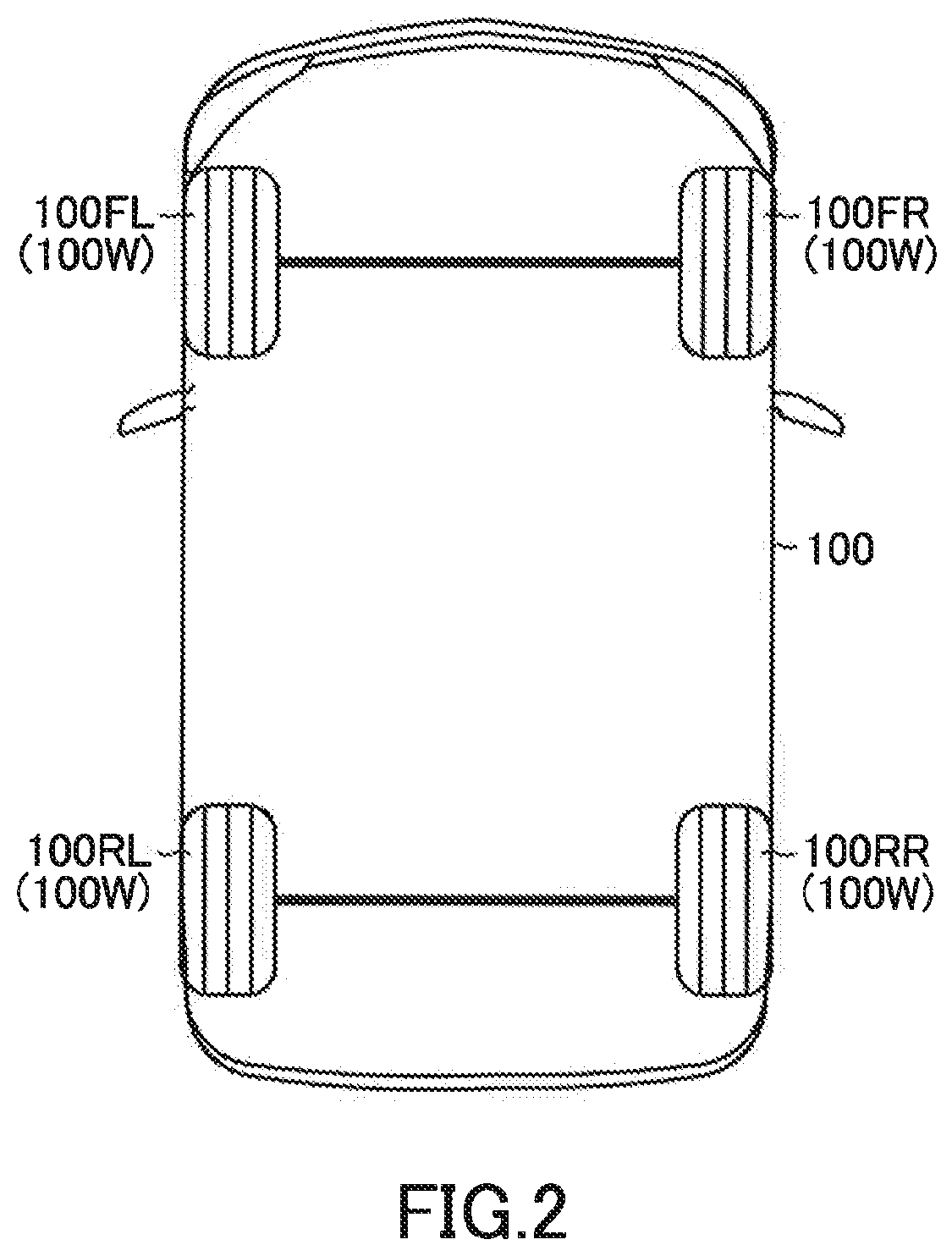
[0054]As shown in FIG. 2, the vehicle 100 includes four road wheels, i.e., a front left wheel 100FL, a front right wheel 100FR, a rear left wheel 100RL, and a rear right wheel 100RR. In this embodiment, the front left wheel 100FL and the front right wheel 100FR are steered wheels as well as driven wheels. In this description, the front left wheel 100FL and the front right wheel 100FR will be collectively referred to as “the front wheels 100F.” Also, the rear left wheel 100RL and the rear right wheel 100RR will be collectively referred to as “the rear wheels 100R.” Also, the front left wheel 100FL, the front right wheel 100FR, the rear left wheel 100RL, and the rear right wheel 100RR will be collectively referred to as “the road wheels 100W.”

[0055]As shown i...


PUM


Abstract

A vehicle control apparatus executes a wheel speed change control to control speeds of first road wheels and a second road wheel to a lower limit wheel speed or more when braking forces are applied to the first and second road wheels, and at least one of the speeds of the first and second road wheels becomes lower than the lower limit wheel speed. A vehicle speed change control executes a first increase-decrease control which alternately executes a first increase control to increase braking forces applied to the first road wheels together and a first decrease control to decrease the braking forces applied to the first road wheels together and (ii) a second increase-decrease control which increases and decreases the braking force applied to the second road wheel.

Description

CROSS-REFERENCE TO RELATED APPLICATIONS[0001]This application claims priority to Japanese patent application No. JP 2020-039755 filed on Mar. 9, 2020, the content of which is hereby incorporated by reference in its entirety.BACKGROUNDField[0002]The present disclosure relates to a vehicle control apparatus.Description of the Related Art[0003]A friction coefficient of a road wheel of a vehicle to a road surface becomes largest when a slip ratio of the road wheel is a certain slip ratio. Hereinafter, the certain slip ratio will be referred to as “the optimum slip ratio.” Therefore, in order to achieve a short braking distance of the vehicle when braking forces are applied to the road wheels to brake the vehicle, the braking forces should be controlled and applied to the road wheels with preventing the slip ratios of the road wheels from exceeding the optimum slip ratio.[0004]In this regard, there is known a vehicle control apparatus which executes a braking force control to control the...

Claims


Application Information

Patent Timeline
Patent Type & Authority Applications(United States)
IPC IPC(8): B60T8/58B60T8/17
CPCB60T8/58B60T8/17B60T2250/04B60T2201/02B60T2240/00B60T8/1761B60T8/17636B60T2220/04
Inventor OTA, JUNYAISONO, HIROSHI
Owner TOYOTA JIDOSHA KK
Why Eureka
Try Eureka