Eureka AIR delivers breakthrough ideas for toughest innovation challenges, trusted by R&D personnel around the world.

Door Hardware Illumination Device

Active Publication Date: 2021-10-14
BROWN MARY ELLEN
View PDF0 Cites 0 Cited by
  • Summary
  • Abstract
  • Description
  • Claims
  • Application Information

AI Technical Summary

Benefits of technology

The present invention is an illuminating device that includes an LED light source, a wireless module, a motion sensor, and a timer circuit. The device can be controlled through a smartphone application and can provide illumination to a desired area. It can be attached to appliances or refrigerators for convenient and safe navigation in dark or dimly lit conditions. The light source can automatically turn on when motion is detected and the battery can be recharged using solar energy. The illuminating device can be easily installed in various shapes and can provide lighting to areas that need to be illuminated for easy access.

Problems solved by technology

In several dwelling areas, it can be hard to find a light source when an individual needs it.
Without proper lighting in dark or dimly lit areas, individuals, both adults and children, may feel nervous, scared or rush to quickly enter a house or an apartment.
Darkness creates additional pressure to quickly find a key and open the door, which can cause anxiety and nervousness amongst individuals.
These lights provide indirect lighting and might offer a broad light source that oftentimes is ineffective for a person attempting to see to access a dwelling.
In such situations, the individual can no longer see the door handle and / or lock to open or unlock the door, which is an inconvenience to the user.
When an individual walks into a dark room at night, it may be difficult to locate light switches or outlets to turn ON the light.
In dark and dimly lit surroundings, individuals, and particularly children, may feel nervous or anxious, or may risk injury if unable to see properly, causing additional inconvenience and discomfort.
Other kinds of lights are also available in the market, but none of the same offer direct lighting to a specific targeted area such as a door handle and / or lock in an entry way.
However, when an individual stands in front of a door to access the handle and / or lock, the light source may be blocked and a shadow may be created on the door, thereby causing a problem in viewing the door handle or knob to unlock the door.
The device does not provide continuous illumination that could interfere with sleeping if installed, for example, in a bedroom.

Method used


Image

  • Door Hardware Illumination Device
  • Door Hardware Illumination Device
  • Door Hardware Illumination Device

Examples


Embodiment Construction

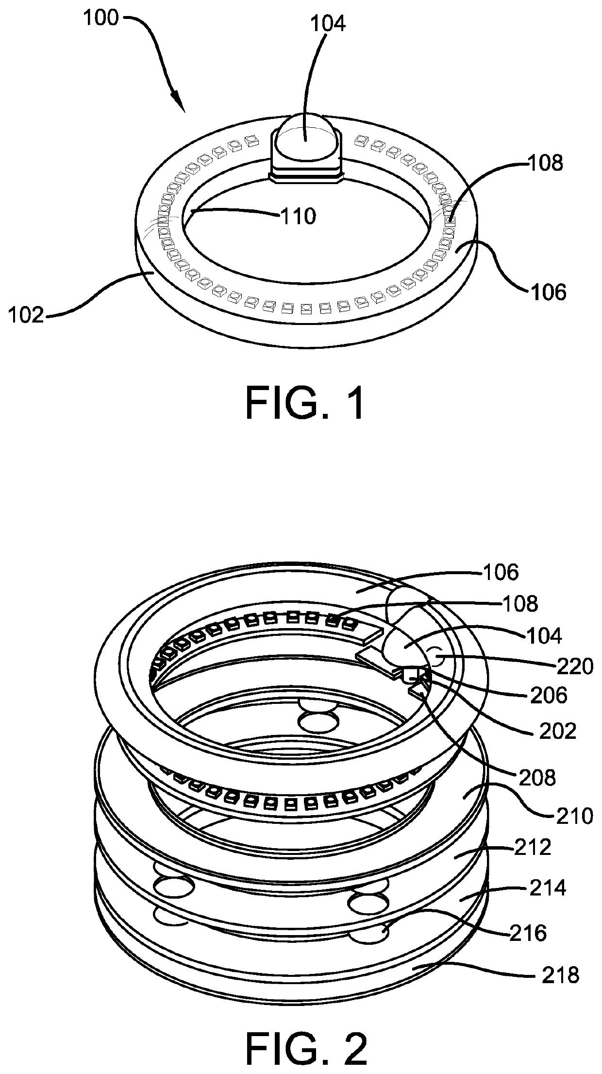
[0025]The innovation is now described with reference to the drawings, wherein like reference numerals are used to refer to like elements throughout. In the following description, for purposes of explanation, numerous specific details are set forth in order to provide a thorough understanding thereof. It may be evident, however, that the innovation can be practiced without these specific details. In other instances, well-known structures and devices are shown in block diagram form in order to facilitate a description thereof. Various embodiments are discussed hereinafter. It should be noted that the figures are described only to facilitate the description of the embodiments. They are not intended as an exhaustive description of the invention and do not limit the scope of the invention. Additionally, an illustrated embodiment need not have all the aspects or advantages shown. Thus, in other embodiments, any of the features described herein from different embodiments may be combined.

[0...


PUM


Abstract

This present invention relates to an illuminated source of light used for illuminating specific areas, such as door handles, door locks, door knobs and more. The source of light comprises an integrated light source, such as a plurality of LED lights, that can be turned ON manually or automatically based on motion detection of an approaching individual or object. Additionally, the source of light may be automatically turned OFF after a predetermined duration of time has elapsed in order to conserve battery life. The illuminated source of light offers a functional and decorative lighting solution for illuminating dark or dimly lit areas, such as dwelling entries.

Description

CROSS-REFERENCE TO RELATED APPLICATION[0001]The present application claims priority to, and the benefit of, U.S. Provisional Application No. 63 / 009,469, which was filed on Apr. 14, 2020 and is incorporated herein by reference in its entirety.FIELD OF THE INVENTION[0002]The present invention relates generally to the field of illuminating devices. More specifically, the present invention relates to an illuminated source of light that is designed to be attached to a door knob, a deadbolt or a door handle. The illuminated source of light can be positioned to illuminate directly at or around the deadbolt, door handle, or other hardware. The illuminated source of light offers a steady glow of light around the door hardware as an individual approaches the door, thereby illuminating dimly lit or dark areas. The illuminated source of light of the present invention provides users with a source of light in various shapes with an integrated light source, including light emitting diode (LED) lig...

Claims


Application Information

Patent Timeline
IPC IPC(8): H05B47/115H05B47/19F21L4/08F21S4/22F21V33/00
CPCH05B47/115H05B47/19F21Y2115/10F21S4/22F21V33/006F21L4/08F21Y2103/33E05B17/10H05B47/17
Inventor BROWN, MARY ELLEN
Owner BROWN MARY ELLEN
Why Eureka
Eureka Blog
Learn More