Imaging system gantry and patient drape

a technology of gantry and patient, applied in the field of medical drapes, can solve the problems of difficult and time-consuming to deploy drapes without breaking sterility, and achieve the effects of fast and easy to remove, easy to deploy, and easy to deploy

Pending Publication Date: 2021-12-30
INSURGERY LLC
View PDF0 Cites 0 Cited by
  • Summary
  • Abstract
  • Description
  • Claims
  • Application Information

AI Technical Summary

Benefits of technology

[0008]It can be difficult and time consuming to deploy drapes without breaking sterility. Featured is a new drape which is fast and easy to deploy, fast and easy to remove, and which can be manufactured inexpensively.

Problems solved by technology

It can be difficult and time consuming to deploy drapes without breaking sterility.

Method used


Image

  • Imaging system gantry and patient drape
  • Imaging system gantry and patient drape
  • Imaging system gantry and patient drape

Examples


Embodiment Construction

[0031]Aside from the preferred embodiment or embodiments disclosed below, this invention is capable of other embodiments and of being practiced or being carried out in various ways. Thus, it is to be understood that the invention is not limited in its application to the details of construction and the arrangements of components set forth in the following description or illustrated in the drawings. If only one embodiment is described herein, the claims hereof are not to be limited to that embodiment. Moreover, the claims hereof are not to be read restrictively unless there is clear and convincing evidence manifesting a certain exclusion, restriction, or disclaimer.

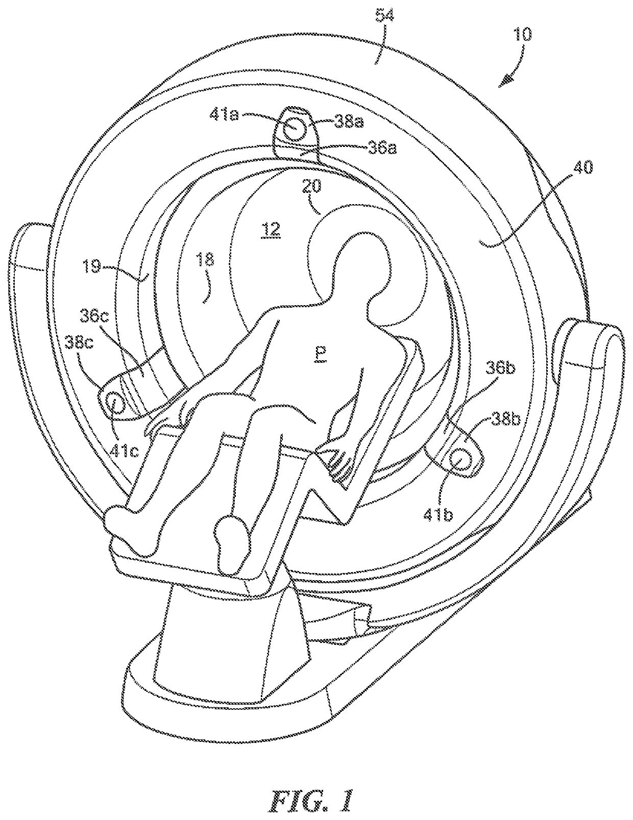
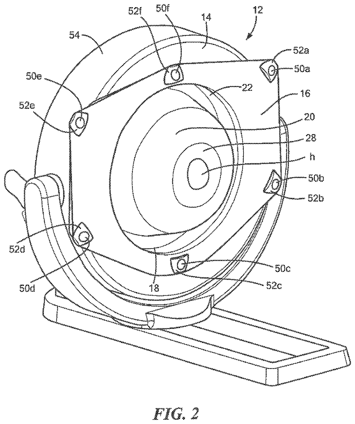
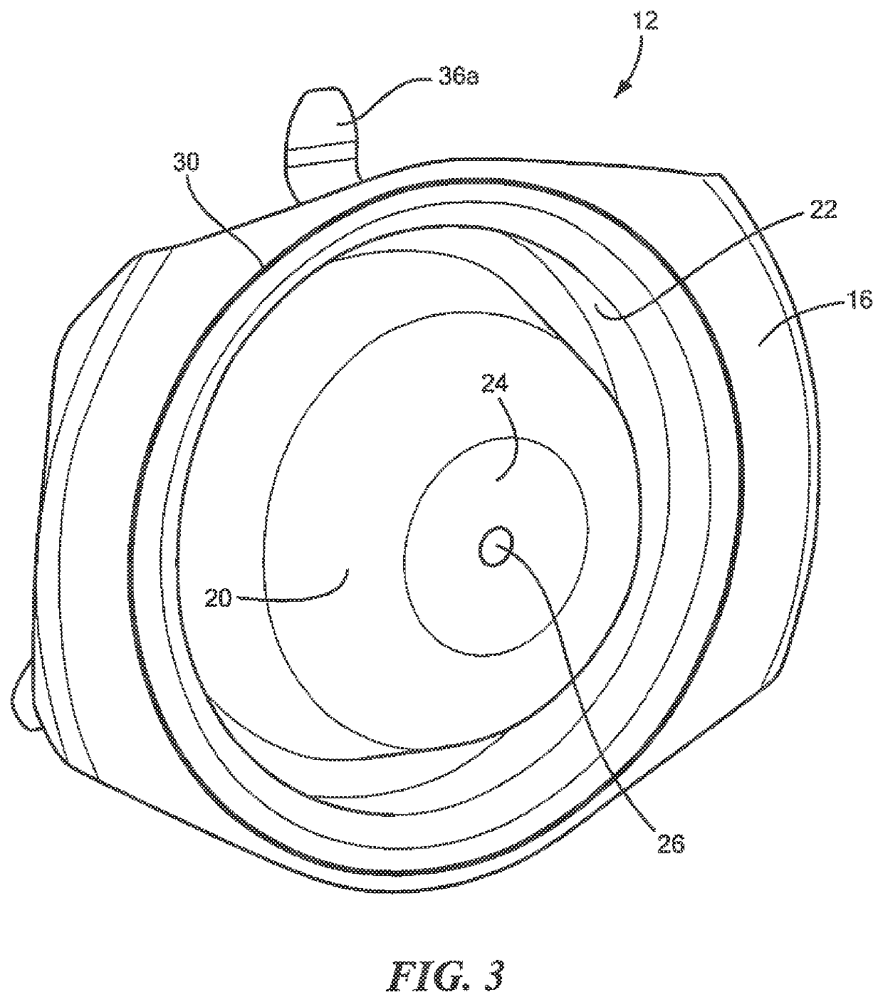
[0032]FIGS. 1-4 show patient P positioned within imaging system gantry 10 for a cranial procedure. Drape 12 is also shown. In this example, imaging system gantry 10 is 0-shaped but the drape can be deployed on C- and other shaped gantries.

[0033]Drape 12 in this example includes gantry first outer sidewall covering portion 1...


PUM


Abstract

An imaging system gantry and patient drape includes a gantry first outer sidewall covering portion biased into a deployed shape and collapsible, a gantry inner wall covering portion extending inward of the gantry first outer sidewall covering portion, and a patient envelope portion. One or more retainers secure a portion of the drape to the gantry. In some versions, one or more drape portions rotate with the gantry and one or more other drape portions do not rotate with the gantry.

Description

RELATED APPLICATIONS[0001]This application claims benefit of and priority to U.S. Provisional Application Ser. No. 63 / 044,490 filed Jun. 26, 2020, under 35 U.S.C. §§ 119, 120, 363, 365, and 37 C.F.R. § 1.55 and § 1.78, and which is incorporated herein by this reference.FIELD OF THE INVENTION[0002]This subject invention relates to medical drapes.BACKGROUND OF THE INVENTION[0003]Imaging systems such as computerized tomography (CT) machines are often used during surgery. A typical CT machine includes an O-shaped gantry with a patient channel therethrough mounted to a gimbal itself mounted to a base. The gimbal can be moved linearly relative to the base. The base may also include a column supporting a patient table which can be moved linearly with respect to the column in and out of the gantry patient channel. See, for example, U.S. Pat. No. 8,770,839 incorporated herein by this reference. Other imaging systems include the Medtronic O-Arm and systems from Siemens, Philips, and Brain Lab...

Claims


Application Information

Patent Timeline
Patent Type & Authority Applications(United States)
IPC IPC(8): A61B46/10A61B6/03A61B6/00
CPCA61B46/10A61B6/4447A61B6/032A61B6/4423A61B6/0478A61B6/4405
Inventor DALEY, II, EDWARD J.STANTON, RUSSELL
Owner INSURGERY LLC
Why Eureka
Try Eureka