Quick-Release Structure for a Display

a display and quick-release technology, applied in the field of quick-release structure for display, can solve the problems of bringing injury to users, reducing cost, display shaking and tilting, etc., and achieve the effect of precise manufacturing and positioning, easy to cause the display to shake and tilting

Active Publication Date: 2022-01-06
JARLLYTEC CO LTD
View PDF6 Cites 1 Cited by
  • Summary
  • Abstract
  • Description
  • Claims
  • Application Information

AI Technical Summary

Benefits of technology

[0004]By means of the structure of the above-mentioned patent with No. CN103388729, it is indeed possible to quickly complete the assembling of the coupling frame and the display, but too many components are required in this patent, which is not conducive to cost reduction. In terms of rotational positioning, the positioning structure of “pin or steel ball plus spring” used in the CN201036450Y requires precise manufacturing and positioning. Any error would easily cause the display to shake and tilt. Furthermore, the three patents with No. CN103388729, No. CN201036450Y and No. CN210567151U all have the buckle arranged on the circumferential side, which is not only abrupt but also easy to cause damage to the devices of these patents or bring injury to users. Accordingly, in order to improve above technical problems, the present invention is provided.
[0005]One object of the present invention is to provide a quick-release structure for a display, which can overcome the problem that too many small components are required in patent with NO. CN103388729, that is, which can effectively decrease the number of required components to reduce production costs. Furthermore, in the present invention, the “first buckling portion” and the “second buckling portion” are provided at corresponding positions to facilitate the corresponding hooking, and the “first buckling portion” and the “pushing portion” are combined to facilitate simultaneous action, such that the quick-release structure of the present invention can be rotated synchronously with the display and the stress can be shared. Moreover, the “first buckling portion” is stored in the “housing of the top base of the stand”. Different from the conventional three patents of No. CN103388729, No. CN201036450Y and No. CN210567151U, where the buckle is arranged on the circumferential side, the arrangement of the buckle arranged on the circumferential side can make it more convenient to proceed the assembling and disassembling of the present invention, and also can protect the “first buckle portion”“and “second buckle portion” to avoid damage caused easily and abruptly to the devices of the present invention or brought injury to users.
[0006]One object of the present invention is to provide a quick-release structure for a display, so as to improve the positioning structure of the “pin or steel ball plus spring” with No. CN201036450Y, which requires precise manufacturing and positioning. Any error would be easy to cause the display shaking and tilting. In the positioning structure, the assembling and positioning are carried out by means of the “several magnetic parts” that form a multi-point mutual positioning via attraction, which is helpful for the rapid attractive positioning via attraction and corresponding hooking, and can also prevent the display from falling off in the unlocking process. There are also grooves and protrusions provided on the corresponding round surface to help confirmation for the positioning. On the other hand, in terms of rotational positioning, the conventional positioning structure can be replaced with “two stoppers”, so as to stop the display when it is rotated vertically or horizontally and to avoid the tilting of the display.

Problems solved by technology

CN103388729, it is indeed possible to quickly complete the assembling of the coupling frame and the display, but too many components are required in this patent, which is not conducive to cost reduction.
Any error would easily cause the display to shake and tilt.
CN210567151U all have the buckle arranged on the circumferential side, which is not only abrupt but also easy to cause damage to the devices of these patents or bring injury to users.
Any error would be easy to cause the display shaking and tilting.

Method used


Image

  • Quick-Release Structure for a Display
  • Quick-Release Structure for a Display
  • Quick-Release Structure for a Display

Examples


Embodiment Construction

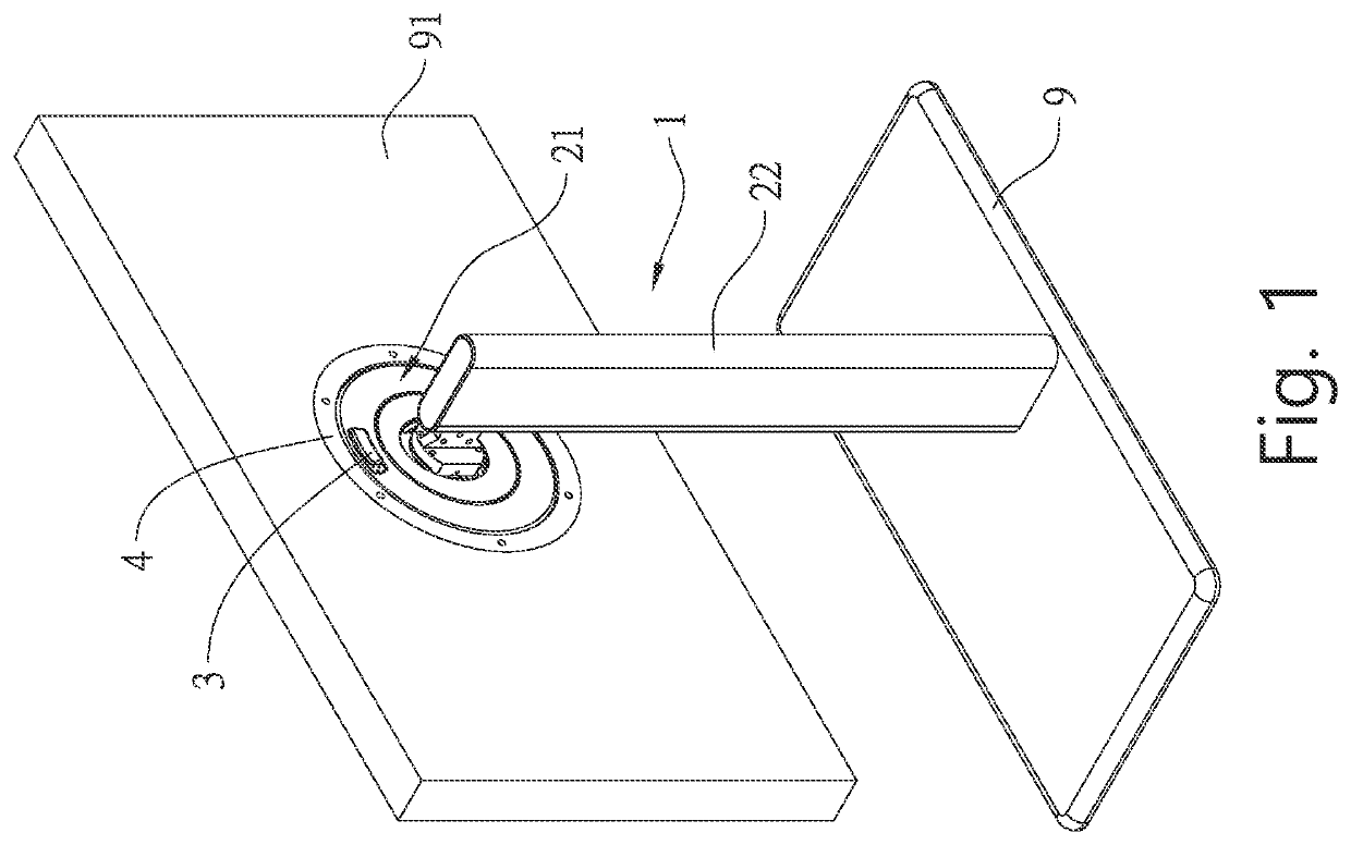
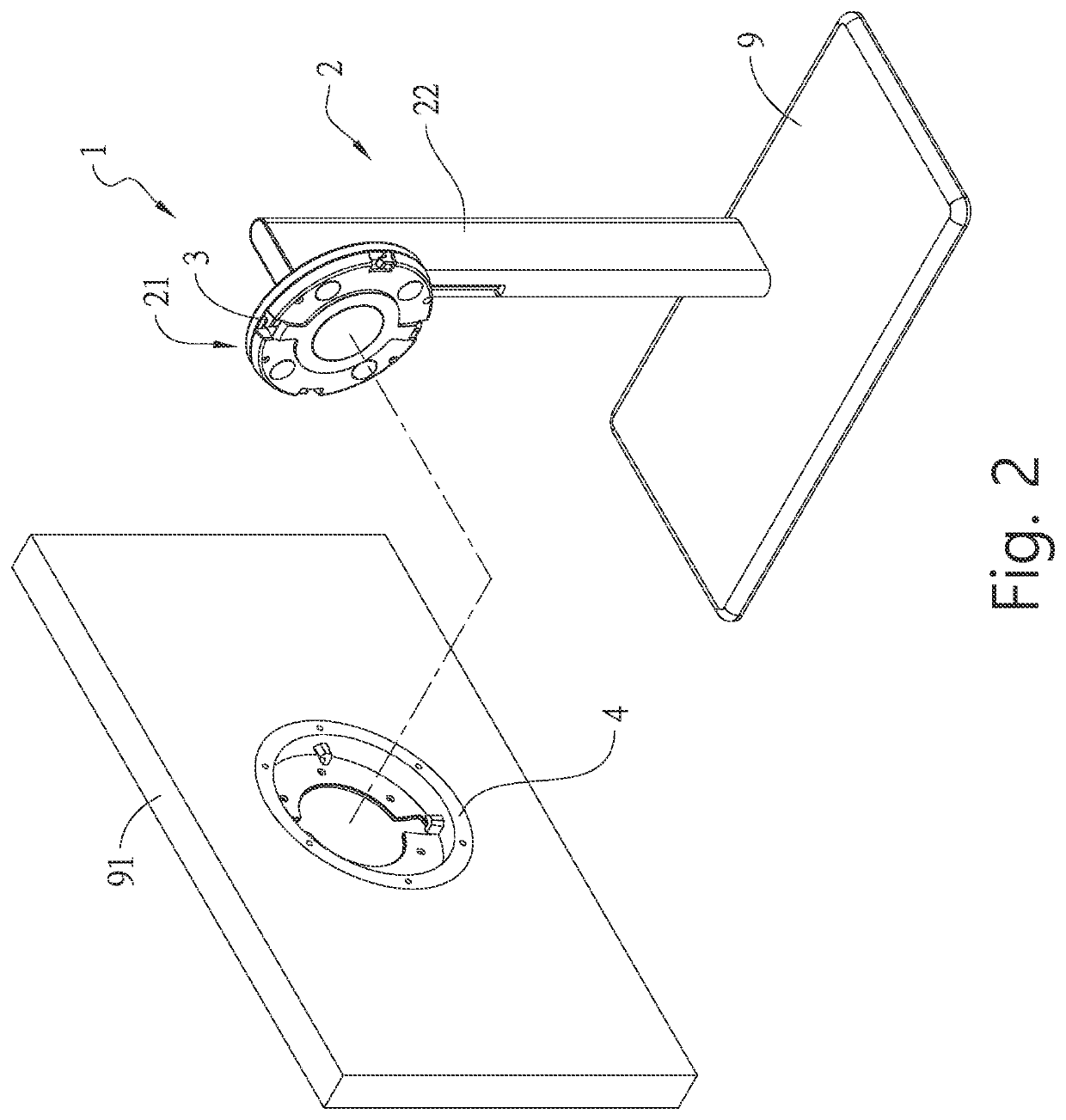
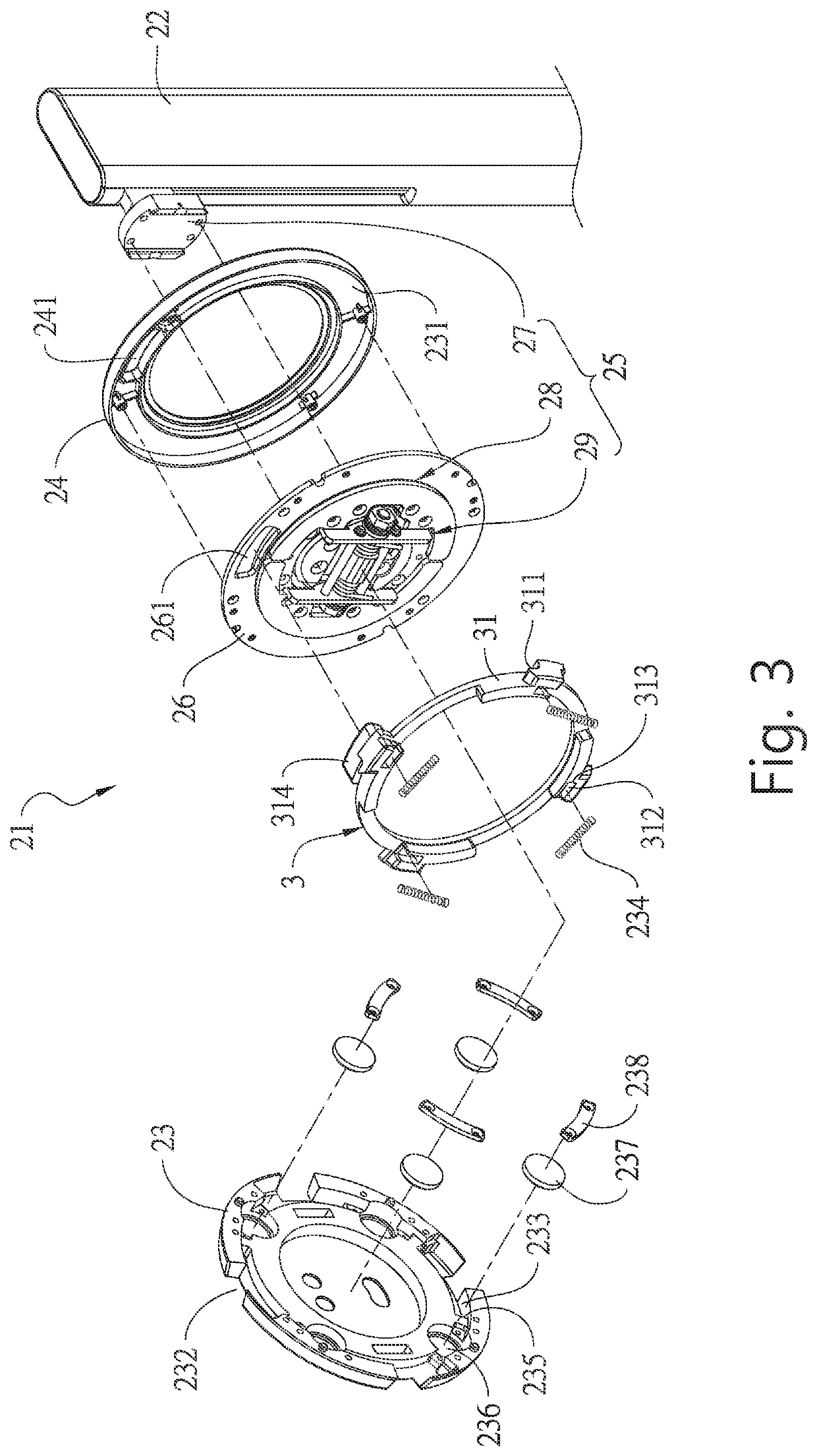
[0028]The quick-release structure for a display provided by the present invention includes a stand. The stand has a top base connected with a side of a top end of a support frame, and the top base has a front cover and a rear cover that cover oppositely each other. The front cover has an outer periphery having a plurality of notches, and the rear cover has one side having a first limiting hole. There is a clamping space between the front cover and the rear cover, and the clamping space accommodates and limits a first buckling ring. The first buckle ring can be actuated by the elastic member to be rotated and then be restored in the clamping space. The first buckle ring has a pushing portion passed through the first limiting hole, such that after the pushing portion is pushed, the first buckle ring is rotated. The first buckle ring further has a plurality of first buckle portions. A second buckle ring is connected with a rear lateral surface of the display. The second buckle ring has...


PUM


Abstract

The present invention provides a quick-release structure for a display, comprising a stand, a first buckle ring and a second buckle ring. The stand includes a top base, and the top base is connected with a side of a top end of a support frame, where the top base has a front cover and a rear cover that cover oppositely each other. A clamping space is provided between the front cover and the rear cover, and the front cover has an outer periphery having a plurality of notches. The first buckle ring, accommodated and limited in the clamping space in a manner that the first buckle ring can be restored after being rotated, where the first buckle ring is provided with a pushing portion passed through the first limiting hole to push the first buckle ring to be rotated.

Description

FIELD OF THE INVENTION[0001]The present invention is related to a quick-release structure for a display, and more particularly to a quick-release structure for quickly assembling and disassembling a stand and a display.BACKGROUND OF THE INVENTION[0002]For an all-in-one computer (AIO, All-in-One) a host is mainly provided on a display, and then the display is combined with the top of a stand through a locking structure provided on the back of the display. In this way, the display is supported by the stand, so that the display can be used on the desktop or flat surface. In this way the connection of the display with the stand through the locking structure makes it very inconvenient and more time-consuming to proceed the assembling and the disassembling.[0003]For example, the Chinese Utility Model Patent entitled with “A screen support structure for easy assembling and disassembling” with No. CN103388729 has disclosed a feasible solution, which includes a stand and a coupling frame. Th...

Claims


Application Information

Patent Timeline
Patent Type & Authority Applications(United States)
IPC IPC(8): F16M11/04G06F1/18F16M11/10
CPCF16M11/041F16M2200/024F16M11/105G06F1/181F16M11/24G06F1/1601G06F2200/1612G06F2200/1614G06F2200/1631G06F1/1626
Inventor HSU, YU-TSUN
Owner JARLLYTEC CO LTD
Why Eureka
Try Eureka