Fluid valve for a vehicle transmission

a technology for vehicle transmissions and valves, applied in valve housings, water supply installations, magnetic bodies, etc., can solve the problems of large electric current, unfavorable pure proportional operation, and possible inability to meet the needs of vehicles, and achieve the effect of easy production

Inactive Publication Date: 2015-01-15
ZF FRIEDRICHSHAFEN AG
View PDF6 Cites 1 Cited by
  • Summary
  • Abstract
  • Description
  • Claims
  • Application Information

AI Technical Summary

Benefits of technology

[0024]In an additional form, the armature is designed in a cylinder shape, with a maximum external diameter, and the second dipping stage is designed in a hollow cylinder shape, with a minimum internal diameter. Thereby, the maximum external diameter of the armature is smaller than the minimum internal diameter of the second dipping stage. Such armature and dipping stages can be easily produced. In one arrangement thereof, upon the dipping of the second tapering

Problems solved by technology

However, in some situations, such a purely proportional manner of operation is not advantageous.
In order to then set a proportional pressure control

Method used


Image

  • Fluid valve for a vehicle transmission
  • Fluid valve for a vehicle transmission
  • Fluid valve for a vehicle transmission

Examples


Embodiment Construction

[0035]Reference will now be made to embodiments of the invention, one or more examples of which are shown in the drawings. Each embodiment is provided by way of explanation of the invention, and not as a limitation of the invention. For example features illustrated or described as part of one embodiment can be combined with another embodiment to yield still another embodiment. It is intended that the present invention include these and other modifications and variations to the embodiments described herein.

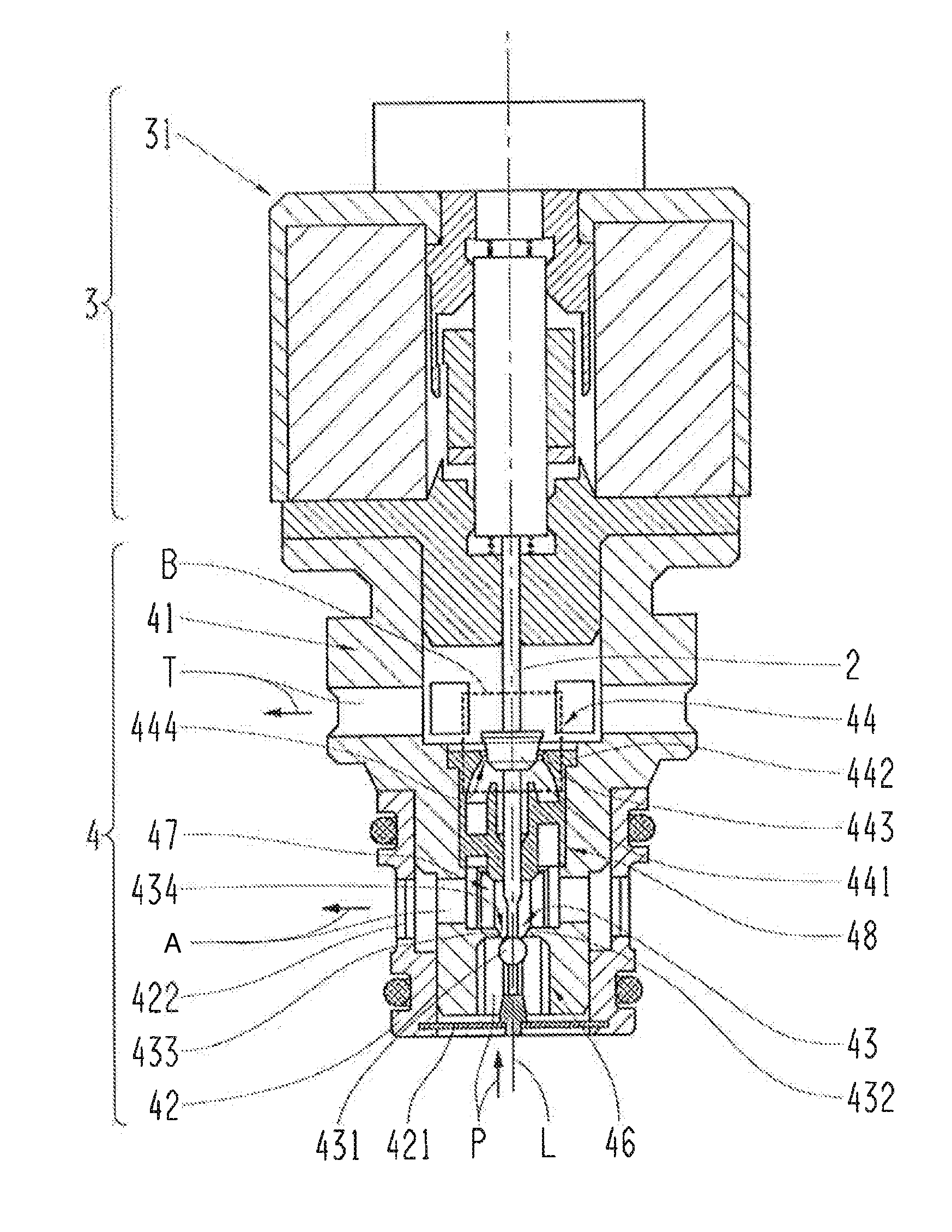
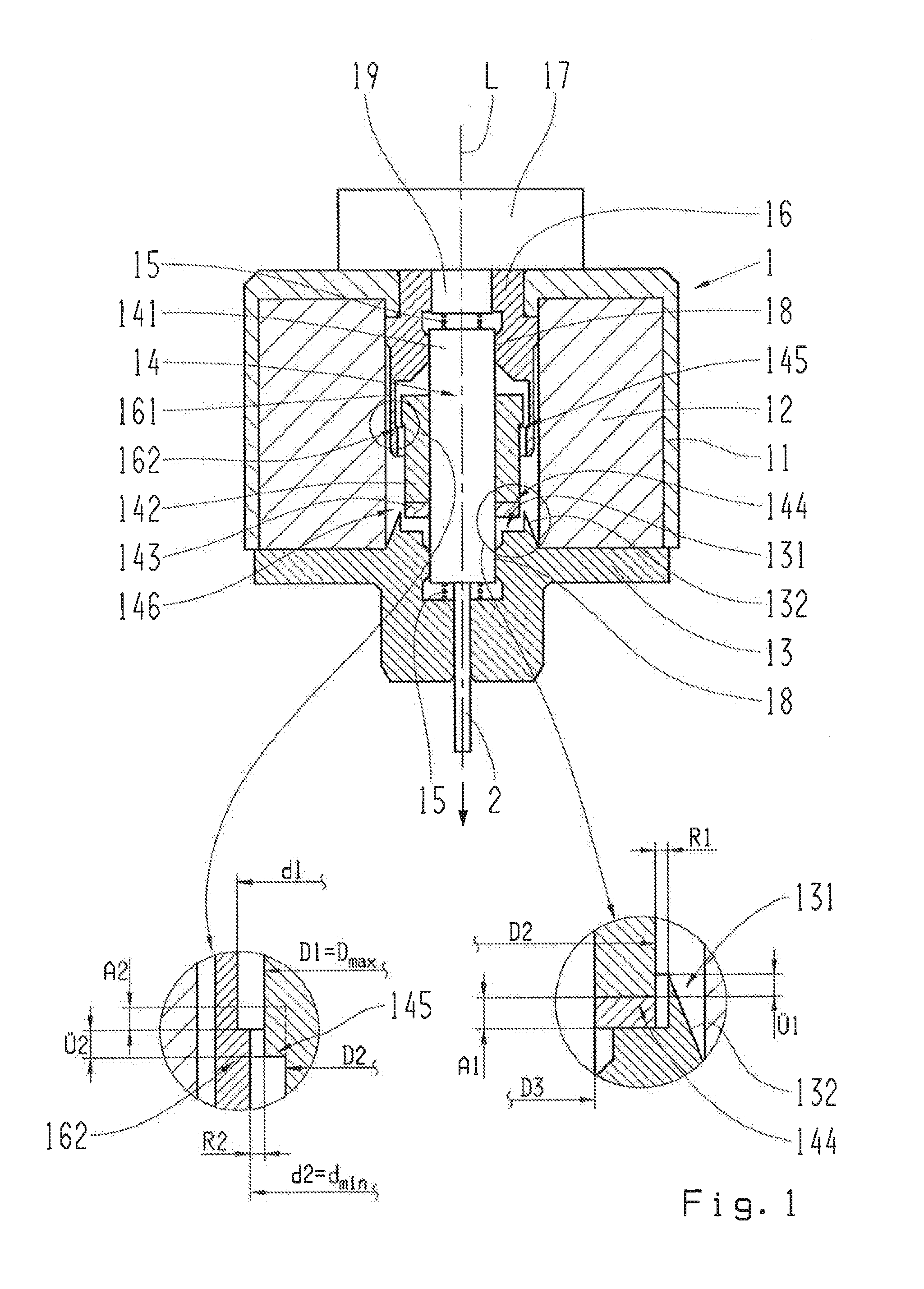
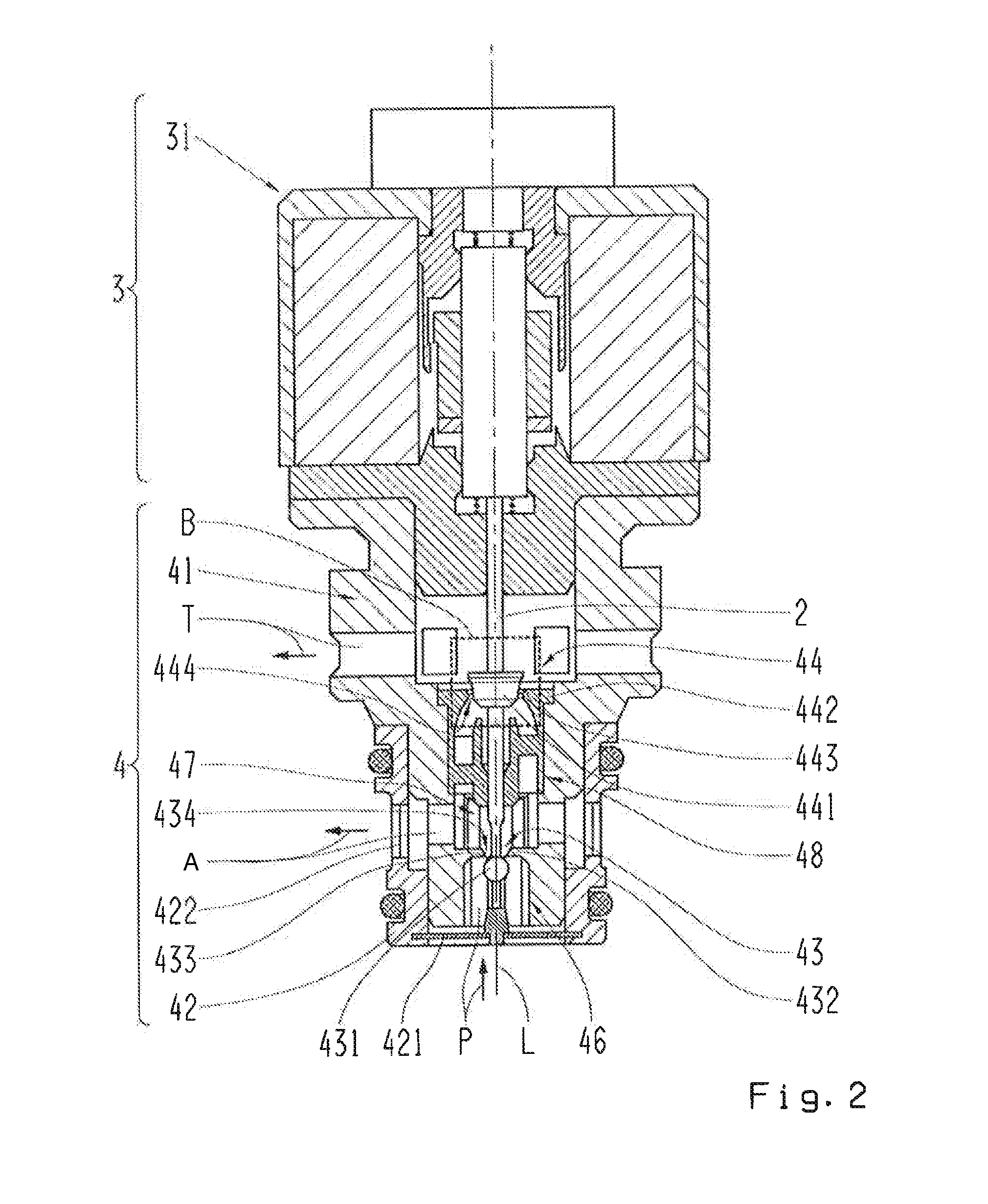
[0036]FIG. 1 shows a longitudinal section through an electromagnetic actuator 1, which is used to actuate a fluid valve, in particular the fluid valve in accordance with the invention. A preferred version of the fluid valve in accordance with the invention is shown in FIG. 2.

[0037]In accordance with FIG. 1, the actuator 1 features a housing 11, a solenoid coil 12, a solenoid armature 14 and a magnetic yoke 13, 16. The first part 13 of the magnetic yoke, which is provided in the are...


PUM


Abstract

A fluid valve, in particular a pressure control valve in a vehicle transmission, has at least one inlet opening and a first and a second outlet opening, which are connected to each other through two part valves that are mechanically coupled to each other. Whereas, by means of the first part valve, a fluid intake is adjustable from the inlet opening to the first and second outlet opening, and, by means of the second part valve, a fluid discharge is adjustable between the first and second outlet opening. At least the second part valve is designed as a poppet valve, with a cone-shaped closing element that features several taper areas, which have varying taper angles.

Description

FIELD OF THE INVENTION[0001]The invention relates to a fluid valve that is particularly useful in a vehicle transmission with at least one inlet opening and one first and second outlet opening, which are able to be connected to each other in terms of flow engineering through part valves that are mechanically coupled to each other. By means of the first part valve, a fluid intake is adjustable from the inlet opening to the first and second outlet opening, and, by means of the second part valve, a fluid discharge is adjustable between the first and second outlet opening, and whereas at least the second part valve is designed as a poppet valve.BACKGROUND[0002]With multi-stage vehicle automatic transmissions and automatic vehicle manual transmissions known from conventional use, hydraulic shifting elements designed as clutches or brakes are used for inserting different transmission stages of the transmission. In this process, for changing or inserting a desired transmission stage of the...

Claims


Application Information

Patent Timeline
IPC IPC(8): F16K15/18F16K31/06
CPCF16K15/183F16K31/06F16K11/048F16K27/029F16K31/0634F16K31/0675H01F7/081H01F7/13H01F2007/1661Y10T137/88054F16K15/1823
Inventor MAYR, KARLHEINZMOOSMANN, MARKUS
Owner ZF FRIEDRICHSHAFEN AG
Why Eureka
Try Eureka