Display with foveated optical correction

Pending Publication Date: 2022-11-03
LUMUS LTD
View PDF0 Cites 0 Cited by
  • Summary
  • Abstract
  • Description
  • Claims
  • Application Information

AI Technical Summary

Problems solved by technology

The larger the field projected, the more complicated it becomes to generate an aberration-free image, or at least, in which aberrations are kept to a level acceptable to the observer.
However, large, complicated and expensive optics are required to maintain a good image a

Method used


Image

  • Display with foveated optical correction
  • Display with foveated optical correction
  • Display with foveated optical correction

Examples


Embodiment Construction

[0045]The present invention is a display system and corresponding methods for displaying an image to an eye of a user.

[0046]The principles and operation of display systems according to the present invention may be better understood with reference to the drawings and the accompanying description.

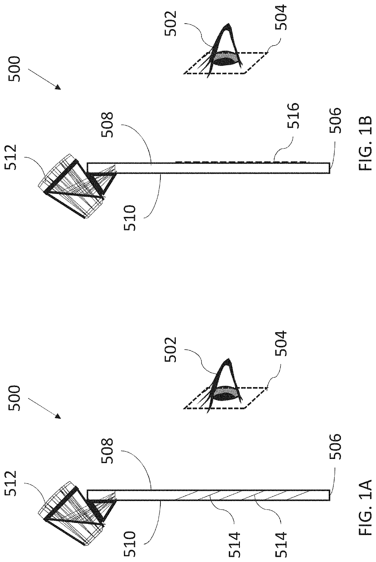
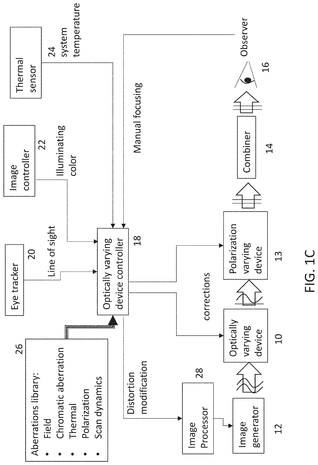
[0047]Referring now to the drawings, FIGS. 1A and 1B show a schematic overview of the major optical components of the system, while FIG. 1C is a block diagram of the system according to certain embodiments of the present invention.

[0048]In general terms, the invention is exemplified herein with reference to a display system 500 for displaying an image to an eye 502 of a user, the eye being located within an eye motion box 504. The display system includes a light-guide optical element (LOE) 506 having a pair of major external surfaces 508, 510 that are parallel to each other. An image projector 512 projecting image illumination of a collimated image is optically coupled to LOE 506 so as to int...


PUM


Abstract

A display system (500) for displaying an image to an eye of a user includes a light-guide optical element (LOE) (506) and an image projector (512) projecting image illumination of a collimated image into the LOE. The image projector includes an electrically-controllable variable lens (10, 13, 71, 77, 58A, 58B, 59, 58C, 58D, 58E, 58F1, 58F2, 58G1, 58G2, 58H, 1223). A controller (18) determines a current region of interest of the image, either from tracking of the user's eye or by analysis of the image content, and controls the variable lens so as to reduce aberrations in the current region of interest at the expense of increased aberration in at least one area of the image outside the current region of interest.

Description

FIELD AND BACKGROUND OF THE INVENTION[0001]Optical systems for near-eye displays project images from a small image generator onto eye-box area (eye-motion box or “EMB”) corresponding to the estimated position of the eye-pupil of the observer. The optics used for this projection typically include some combination of mirrors, lenses and prisms. The image is typically delivered to the observer's eye by a combiner based on a transparent waveguide or a transparent reflector.[0002]The optical arrangement is optimized to reduce optical aberrations in the projected image, including defocus, spherical, coma, astigmatism and more.[0003]The larger the field projected, the more complicated it becomes to generate an aberration-free image, or at least, in which aberrations are kept to a level acceptable to the observer. The optical system can be optimized for minimal aberrations at the center of the field. However, large, complicated and expensive optics are required to maintain a good image all ...

Claims


Application Information

Patent Timeline
IPC IPC(8): G02F1/29F21V8/00G02B27/00G02F1/01G06F3/01G06V10/25H04N9/31
CPCG02F1/294G02B6/0031G02B27/0093G02F1/0136G02B6/003G06F3/013G06V10/25H04N9/317H04N9/3161G02B27/0172G02B3/14G02B5/3083G02B2027/0187G02B2027/0116G02B26/101G02B26/0816G02B2027/0147
Inventor DANZIGER, YOCHAY
Owner LUMUS LTD
Why Eureka
Try Eureka