System and method for using diffractive elements for changing the optical pathway

a diffractive element and optical pathway technology, applied in the field of optical imaging, can solve the problems of limiting the integration of a focus and/or optical zoom system, unable to produce focused images for fixed focus lens cameras, and unable to change the focus, so as to reduce at least some optical aberrations of images

Inactive Publication Date: 2009-07-16
SAMSUNG ELECTRONICS CO LTD
View PDF1 Cites 2 Cited by
  • Summary
  • Abstract
  • Description
  • Claims
  • Application Information

AI Technical Summary

Benefits of technology

[0048]Optionally, the diffractive optics element is configured for reducing at least some optical aberrations of the image caused by diffraction.

Problems solved by technology

The limited focal axis of such lenses limits the integration of a focus and / or optical zoom systems.
Usually, fixed focus lens cameras do not produce focused images of objects whose distance from the lens is less than 0.5 meter and do not allow changing the focus during the image capturing process.
Because interpolation disturbs the original pixel layout of the image, as captured by the camera's image capturing sensor, it is usually considered detrimental to image quality.
Zoom lenses, however, require a certain size along their focal axis, that makes them unfit for mobile phone cameras.
Such a size is generally too large for mobile phone cameras.

Method used


Image

  • System and method for using diffractive elements for changing the optical pathway
  • System and method for using diffractive elements for changing the optical pathway
  • System and method for using diffractive elements for changing the optical pathway

Examples


Embodiment Construction

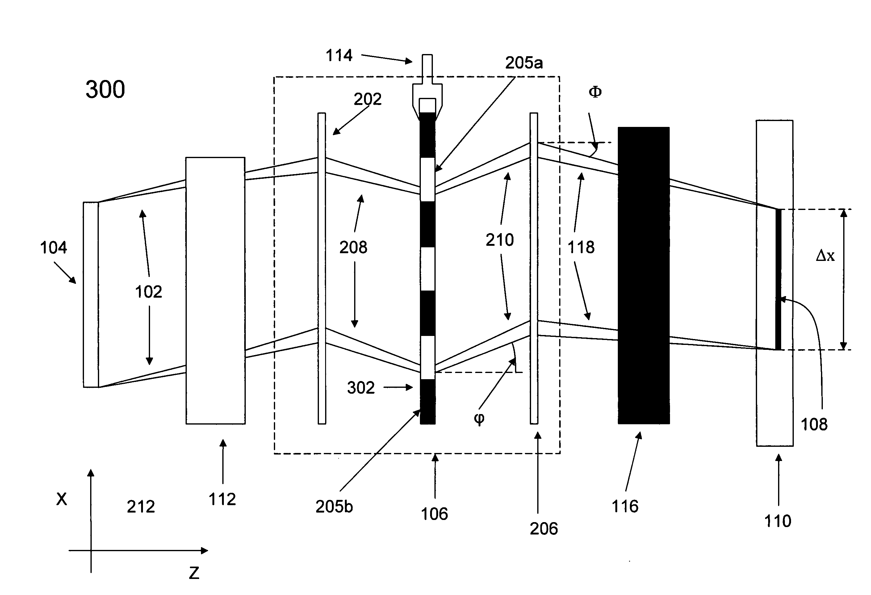
[0063]The present invention, in some embodiments thereof, relates to optical imaging and, more particularly, but not exclusively, to a system for forming a multispectral image of an object. The present invention is applicable to, but not limited to, the imaging, focusing, and zooming functions in cameras, and more particularly, in cameras incorporated into cellular phones. Other applications include, but are not limited to, projecting images of objects, and adjusting the size and focus of the projected images.

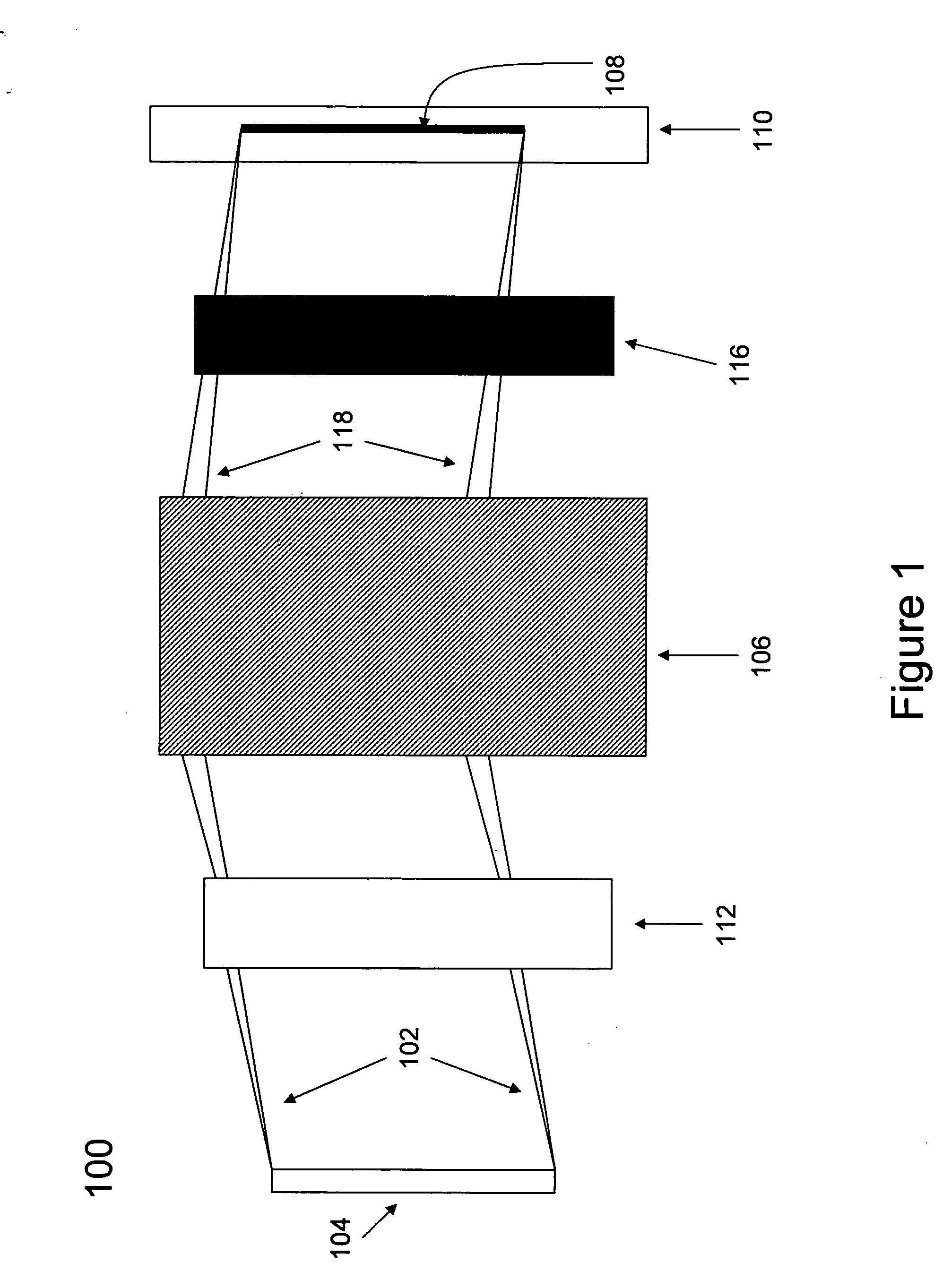
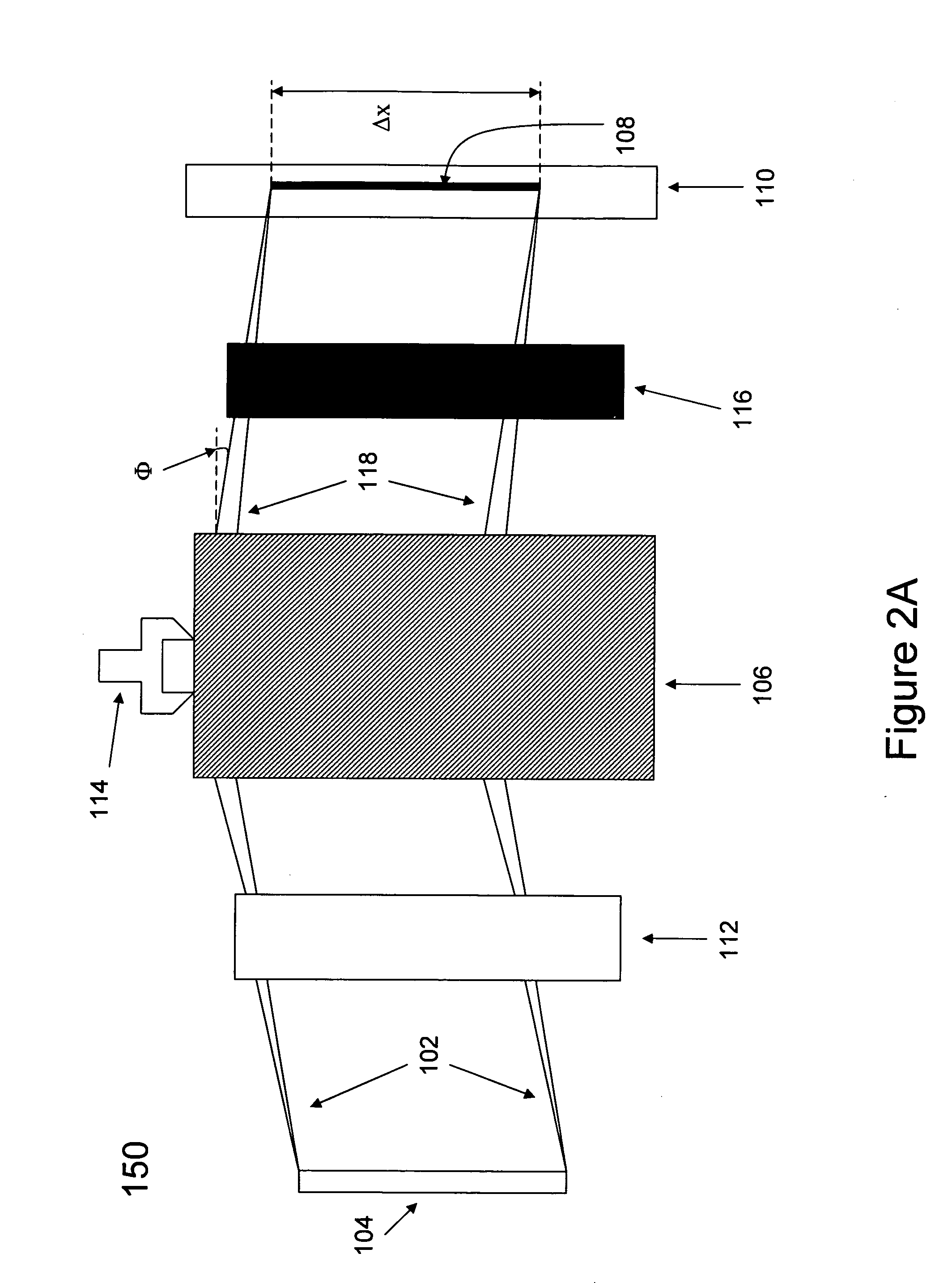
[0064]Some of the present embodiments of the invention relate to an image capturing device, which comprises one or more diffractive optics elements and an image capturing sensor. The diffractive optics element diffracts light leaving an object, and creates an image of the object on the image capturing sensor. Optionally, all the optical elements of the device are diffractive optics elements and all the optical functions which are performed by of the device are performed by the ...


PUM


Abstract

An apparatus for adjusting an optical pathway, comprising a diffractive optics element configured for diffracting a plurality of light waves passing in the optical pathway, and a diffractive optics element (DOE) manipulator configured for manipulating said diffractive optics element, thereby changing the optical pathway.

Description

RELATIONSHIP TO EXISTING APPLICATIONS[0001]This application is a continuation-in-part of U.S. patent application Ser. No. 12 / 007,879, filed on Jan. 16, 2008, the contents of which are hereby incorporated by reference.FIELD AND BACKGROUND OF THE INVENTION[0002]The present invention, in some embodiments thereof, relates to optical imaging and, more particularly, but not exclusively, to a system for forming a multispectral image of an object. The present invention is applicable to, but not limited to, the imaging, focusing, and zooming functions in cameras, and more particularly, in cameras incorporated into cellular phones. Other applications include, but are not limited to, projecting images of objects, and adjusting the size and focus of the projected images.[0003]In today's market, Image capturing devices are becoming more and more compact, and some are incorporated into thin devices, such as mobile phones, personal digital assistants (PDAs) and other hand-held devices, as well as ...

Claims


Application Information

Patent Timeline
Patent Type & Authority Applications(United States)
IPC IPC(8): G02B27/44G02B27/42
CPCG02B5/32G02B27/4211G03H2227/03G02B27/4272G02B27/4294G02B27/4216
Inventor SADE, SHARONSOREK, NOAM
Owner SAMSUNG ELECTRONICS CO LTD
Why Eureka
Try Eureka