Enhanced variable power zoom lens

a variable power and zoom lens technology, applied in the field of compact and enhanced variable power zoom lenses, can solve the problems of user's hands shaking during photographing, difficult to achieve instantaneous focusing, etc., and achieve the effect of reducing aberration

Active Publication Date: 2013-05-28
TAMRON +1
View PDF28 Cites 54 Cited by
  • Summary
  • Abstract
  • Description
  • Claims
  • Application Information

AI Technical Summary

Benefits of technology

[0028]The enhanced variable power zoom lens according to the present invention is configured as mentioned above so as to reduce weight in whole and in part, especially, having its focusing lens optics lightened to relieve of a load on a focusing drive system and having its anti-vibration lens optics reduced in both diameter and weight to relieve of a load on an anti-vibration drive system, thereby attaining the downsizing of the anti-vibration drive system.
[0046]In this aspect, the fourth lens group G4 with the lens piece having at least one of its major surfaces made aspherical is capable of inhibiting well from varying in spherical aberration and comatic aberration throughout the entire range of an object distance. Thus, configured in this manner, the zoom lens can effectively produce a clear image with the reduced aberration.

Problems solved by technology

When designed in an application of an auto-focusing zoom lens, the upfront lens focusing zoom lens must have its large and heavy foremost lens group moved along the optical axis, and this makes it difficult to achieve instantaneous focusing.
On the other hand, there generally arises a problem with such an enhanced variable power zoom lens that user's hands are liable to shake during photographing at the telephoto end.

Method used


Image

  • Enhanced variable power zoom lens
  • Enhanced variable power zoom lens
  • Enhanced variable power zoom lens

Examples


embodiment 1

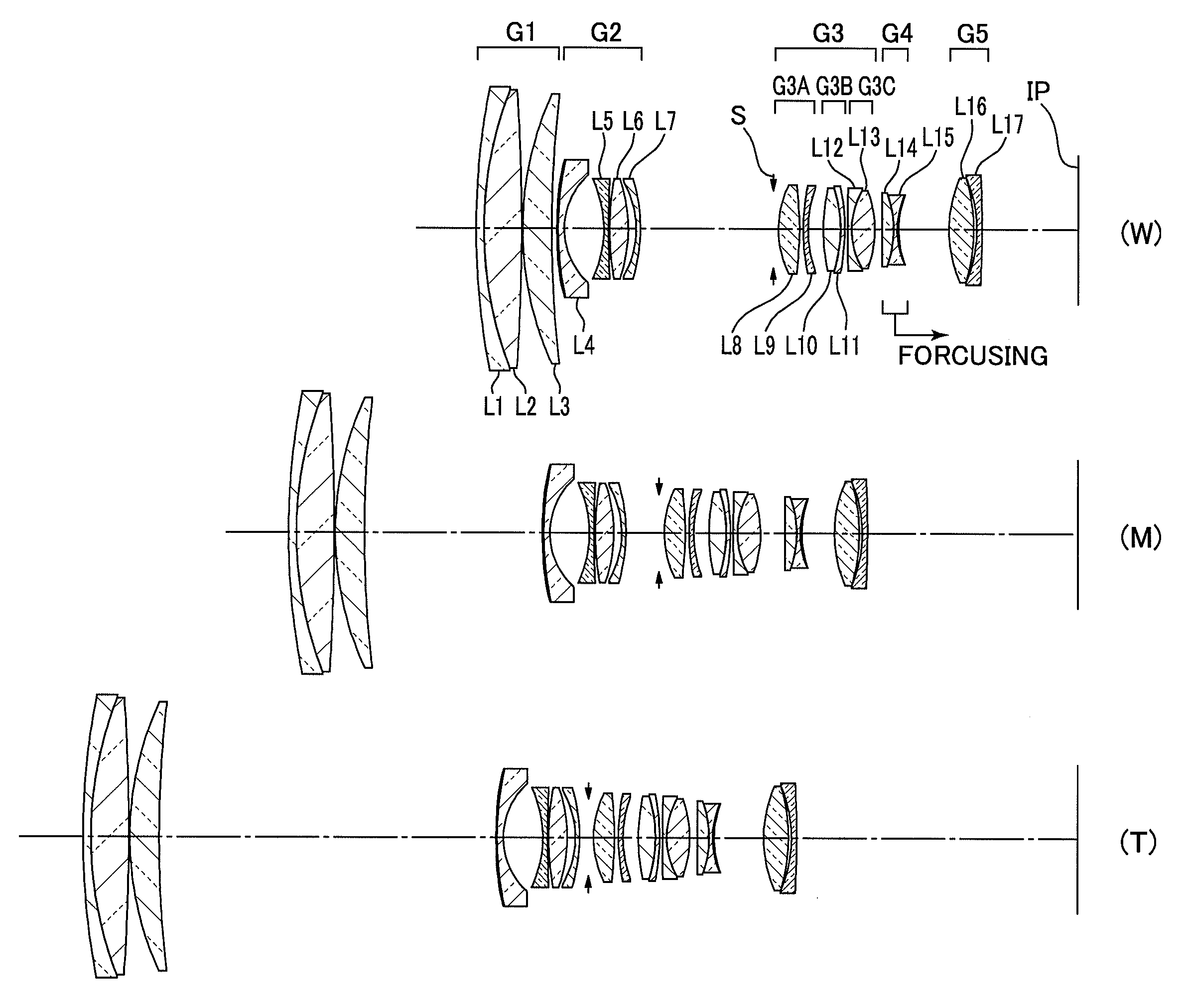
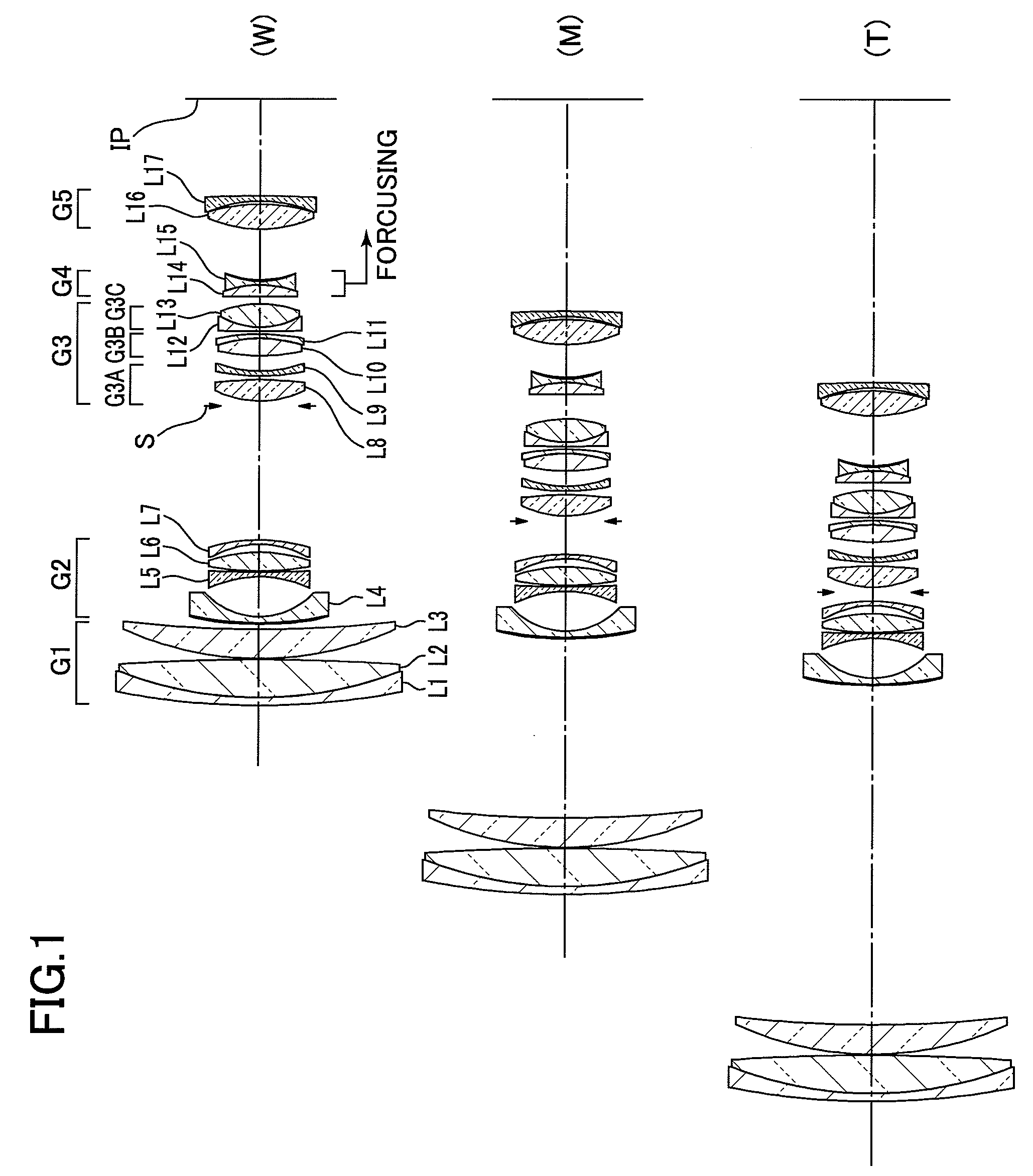
[0078]A first embodiment of an enhanced variable power zoom lens consists of the foremost or first lens group G1 of positive refractivity, the second lens group G2 of negative refractivity, the third lens group G3 of positive refractivity, the fourth lens group G4 of negative refractivity, and the fifth lens group G5 of positive refractivity arranged in sequence from a position closer to the object.

[0079]The first lens group G1 consists of a composite lens of a negative meniscus lens piece L1 having its convex surface directed toward the object and a double-convex lens piece L2, and a positive meniscus lens L3 having its convex surface directed toward the object.

[0080]The second lens group G2 consists of a negative meniscus lens L4 having its convex surface directed toward the object, a double-concave lens L5, a double-convex lens L6, and a negative meniscus lens L7 having its convex surface directed toward the image plane. The negative meniscus lens L4 positioned the closest to the...

embodiment 2

[0095]A second embodiment of the enhanced variable power zoom lens according to the present invention consists of the foremost or first lens group G1 of positive refractivity, the second lens group G2 of negative refractivity, the third lens group G3 of positive refractivity, the fourth lens group G4 of negative refractivity, and the fifth lens group G5 of negative refractivity arranged in sequence from a position closer to the object.

[0096]The first lens group G1 consists of a composite lens of a negative meniscus lens piece L1 having its convex surface directed toward the object and a double-convex lens piece L2, and a positive meniscus lens L3 having its convex surface directed toward the object.

[0097]The second lens group G2 consists of a negative meniscus lens L4 having its convex surface directed toward the object, a double-concave lens L5, a double-convex lens L6, and a negative meniscus lens L7 having its convex surface directed toward the image plane arranged in sequence fr...

embodiment 3

[0113]A third embodiment of the enhanced variable power zoom lens according to the present invention consists of the foremost or first lens group G1 of positive refractivity, the second lens group G2 of negative refractivity, the third lens group G3 of positive refractivity, the fourth lens group G4 of negative refractivity, and the fifth lens group G5 of positive refractivity arranged in sequence from a position closer to the object.

[0114]The first lens group G1 consists of a composite lens of a negative meniscus lens piece L1 having its convex surface directed toward the object and a double-convex lens piece L2, and a positive meniscus lens L3 having its convex surface directed toward the object.

[0115]The second lens group G2 consists of a negative meniscus lens L4 having its convex surface directed toward the object, a negative meniscus lens L5 having its convex surface directed toward the image plane, a double-convex lens L6, and a negative meniscus lens L7 having its convex sur...


PUM


Abstract

The present invention is directed to provide an enhanced variable power zoom lens that is lightweight as a whole, and especially, has its focusing lens optics reduced in weight so as to relieve of a load on a focusing drive system, and that has its anti-vibration lens optics reduced in both diameter and weight so as to relieve of a load on an anti-vibration drive system and downsize the same. The enhanced variable power zoom lens is adapted to have the foremost or first lens group of positive refractivity, the second lens group of negative refractivity, the third lens group of positive refractivity, the fourth lens group of negative refractivity, and the fifth lens group arranged in this sequence from a position closer to the object where a distance between each pair of the adjacent lens groups is varied during zooming from the wide-angle end to the telephoto end, each lens group comes closer to the object at the telephoto end than at the wide-angle end, the third lens group and the fourth lens group separating the farthest apart from each other at the intermediate zooming range, and the fourth lens group is moved closer to the image plane for shifting from infinity focusing to proximity focusing.

Description

FIELD OF THE INVENTION[0001]The present invention relates to a compact and enhanced variable power zoom lens having a zoom ratio of 10× or even greater and an angle of view of 75 degrees or even wider at the wide-angle end, which is suitable for use in 35 mm cameras, video cameras, electronic still cameras, and the like.BACKGROUND ART[0002]As one example of prior art focusing systems for a zoom lens, an upfront lens focusing system is well-known in the art where the foremost group of lens pieces positioned the closest to the object to photograph is displaced for focusing. When designed in an application of an auto-focusing zoom lens, the upfront lens focusing zoom lens must have its large and heavy foremost lens group moved along the optical axis, and this makes it difficult to achieve instantaneous focusing.[0003]In order to overcome the aforementioned disadvantage, inner and rear focusing systems that force the second foremost lens group and / or the further succeeding one(s) are to...

Claims


Application Information

Patent Timeline
Patent Type & Authority Patents(United States)
IPC IPC(8): G02B9/60
CPCG02B15/173G02B15/145105
Inventor YAMANAKA, HISAYUKIKANAI, MAKOTOSUEYOSHI, MASAFUMIHOSOI, MASAHARU
Owner TAMRON
Why Eureka
Try Eureka