Image processing device and image pickup device using the same

a technology of image processing and image pickup, which is applied in the direction of image enhancement, instruments, television systems, etc., can solve the problem of inability to correct the difference between amplitude components in azimuthal directions, and achieve the effect of reducing an asymmetry aberration and higher-accuracy images

Active Publication Date: 2011-11-24
CANON KK
View PDF4 Cites 50 Cited by
  • Summary
  • Abstract
  • Description
  • Claims
  • Application Information

AI Technical Summary

Benefits of technology

[0013]The present invention has been made in view of the above problem, and an object of the present invention is to provide an image processing device which reduces an asymmetry aberration which is likely to occur due to an image restoration process so as to obtain a higher-accuracy image.

Problems solved by technology

However, when the Wiener filter or the image restoration filter disclosed in Patent Literature 1 is used, deterioration of amplitude components and phase components in an image pickup optical system may be corrected but a difference between amplitude components in azimuthal directions may not be corrected.

Method used


Image

  • Image processing device and image pickup device using the same
  • Image processing device and image pickup device using the same
  • Image processing device and image pickup device using the same

Examples


first embodiment

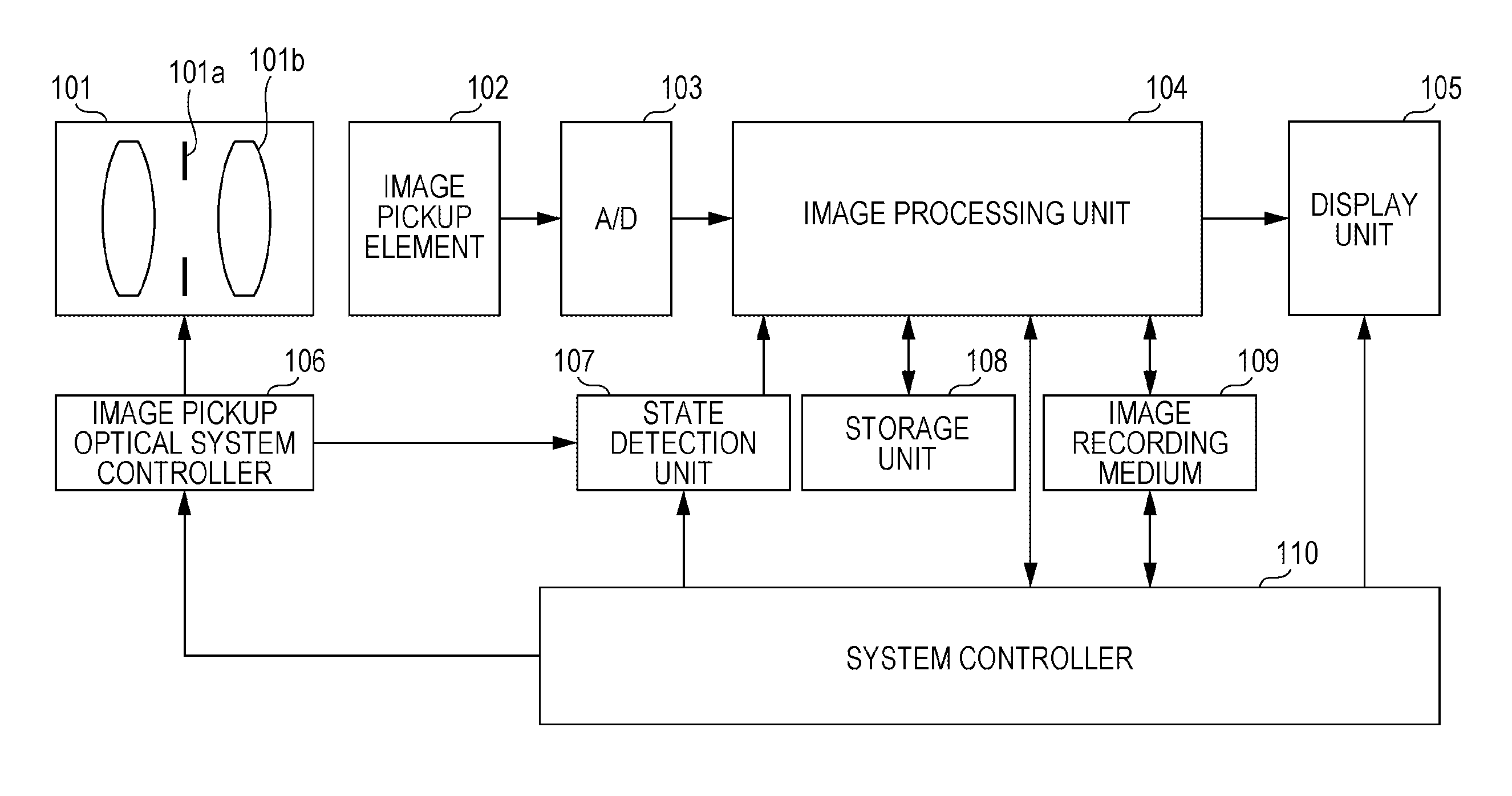
[0092]FIG. 5 is a diagram schematically illustrating a configuration of an image pickup device according to a first embodiment. An object image not shown is formed on an image pickup element 102 using an image pickup optical system 101. The image pickup element 102 converts formed light into an electric signal (photoconversion), and an A / D converter 103 converts the electric signal into a digital signal. Then, an image processing unit 104 performs an image process on the digital signal (input image) in addition to predetermined processes. Here, the predetermined processes include electric aberration correction such as correction of a magnification chromatic aberration, correction of a distortion aberration, and correction of a peripheral brightness, demosaicing, gamma conversion, and image compression.

[0093]First, image pickup state information of the image pickup device is obtained from a state detection unit 107. The state detection unit 107 may obtain the image pickup state infor...

second embodiment

[0115]FIG. 11A is a diagram illustrating a configuration of an image processing system according to a second embodiment of the present invention. An image processing device 111 is constituted by an information processing apparatus and includes image processing software (image processing program) 112 which causes the information processing device to execute the image processing method described in the first embodiment.

[0116]An image pickup device 113 includes a camera, a microscope, an endoscope, a scanner, and the like. A storage medium 114 corresponding to a semiconductor memory, a hard disk, a server on a network, or the like stores an image (captured image data) generated by image capturing.

[0117]The image processing device 111 obtains image data from the image pickup device 113 or the storage medium 114 and output image (corrected image) data obtained through a predetermined image process to at least one of an output device 116, the image pickup device 113, and the storage mediu...

third embodiment

[0136]In the third embodiment, an example of a process of generating a more appropriate image using the image restoration filters according to the first and second embodiments will be described. By performing the process of this embodiment, a restored image having image quality of a high degree of freedom can be generated. The third embodiment will be described with reference to the accompanying drawings.

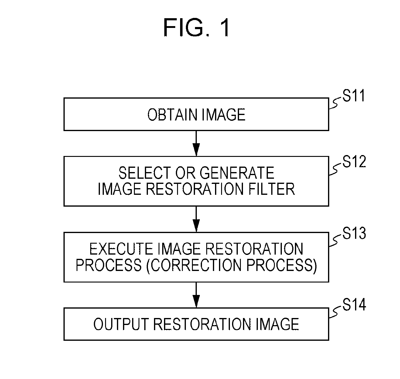
[0137]FIG. 13 shows a flow of an image processing method executed in this embodiment. In a description below, a reference character m denotes a color component (R, G, or B, for example) of an image. Specifically, “Am” denotes AR, AG, and AB corresponding to an R component of A, a G component of A, and a B component of A, respectively. “A” corresponds to g, f, fd, S, Sd, and the like shown in FIG. 13.

[0138]A first restoration process is performed on an input image gm having the color components R, G, and B using image restoration filters selected or generated for individual color com...


PUM


Abstract

An image processing device capable of obtaining a high precision image while aberration asymmetry is corrected.An image processing device includes image obtaining means configured to obtain an input image, image restoration means configured to restore the input image using a generated or selected image restoration filter in accordance with a transfer function of an image pickup system used for forming the input image from an object image. The image restoration filter makes a difference between absolute values of transfer functions of two azimuthal directions at a time when the restoration image is obtained from an object smaller than a difference between absolute values of transfer functions of the two azimuthal directions of the image pickup system.

Description

CROSS-REFERENCE TO RELATED APPLICATIONS[0001]This application is a Continuation of International Patent Application No. PCT / JP2011 / 055610, filed Mar. 10, 2011, which claims the benefit of International Patent Application No. PCT / JP2010 / 055865, filed Mar. 31, 2010 and Japanese Patent Application No. 2010-082832, filed Mar. 31, 2010, all of which are hereby incorporated by reference herein in their entirety.TECHNICAL FIELD[0002]The present invention relates to image processing devices which perform image processing and particularly relates to an image processing device which performs image restoration.BACKGROUND ART[0003]Images obtained by image pickup devices such as digital still cameras are deteriorated due to image blurs. The blurs of images are caused by a spherical aberration, a comatic aberration, field curvature, astigmatism, and the like. These aberrations may be represented by a PSF (Point Spread Function). An OTF (Optic Transfer Function) obtained by performing Fourier tran...

Claims


Application Information

Patent Timeline
Patent Type & Authority Applications(United States)
IPC IPC(8): H04N5/217G06K9/40
CPCG06T5/003H04N5/3572H04N5/217H04N9/646G06T5/001H04N9/045H04N25/611H04N23/81
Inventor HATAKEYAMA, KOSHI
Owner CANON KK
Why Eureka
Try Eureka