System and method for laser generated corneal and crystalline lens incisions using a variable f/# optical system with aspheric contact interface to the cornea or rotating and adaptive optics

a technology of variable f/# and optical system, which is applied in the field of system and method of laser generated corneal and crystalline lens incisions, can solve the problems of difficult design of optical system capable of focusing beam over a large three-dimensional area, high cost, and high cost, and achieves significant flexibility, reduces the complexity of optics, and reduces the number of moving elements.

Active Publication Date: 2012-10-25
LENSAR LLC
View PDF11 Cites 53 Cited by
  • Summary
  • Abstract
  • Description
  • Claims
  • Application Information

AI Technical Summary

Benefits of technology

[0019]One or more aspects of the present invention allow for a reduction in the complexity of optics in an ophthalmic beam delivery optical system. Another advantage of this present invention is that the adaptive optic device allows for significant

Problems solved by technology

Arbitrarily complex incision patterns can be generated with such lasers.
However, low F/# systems are very susceptible to optical aberrations as the laser beam passes through the optics and the transparent tissue of the eye.
Since creating incisions in the cornea and lens requires focusing relatively deep into the tissue, focusing considerably off axis and crossing curved interfaces between transparent materials, it is very challenging to design an optical system capable of focusing a beam o

Method used


Image

  • System and method for laser generated corneal and crystalline lens incisions using a variable f/# optical system with aspheric contact interface to the cornea or rotating and adaptive optics
  • System and method for laser generated corneal and crystalline lens incisions using a variable f/# optical system with aspheric contact interface to the cornea or rotating and adaptive optics
  • System and method for laser generated corneal and crystalline lens incisions using a variable f/# optical system with aspheric contact interface to the cornea or rotating and adaptive optics

Examples


Embodiment Construction

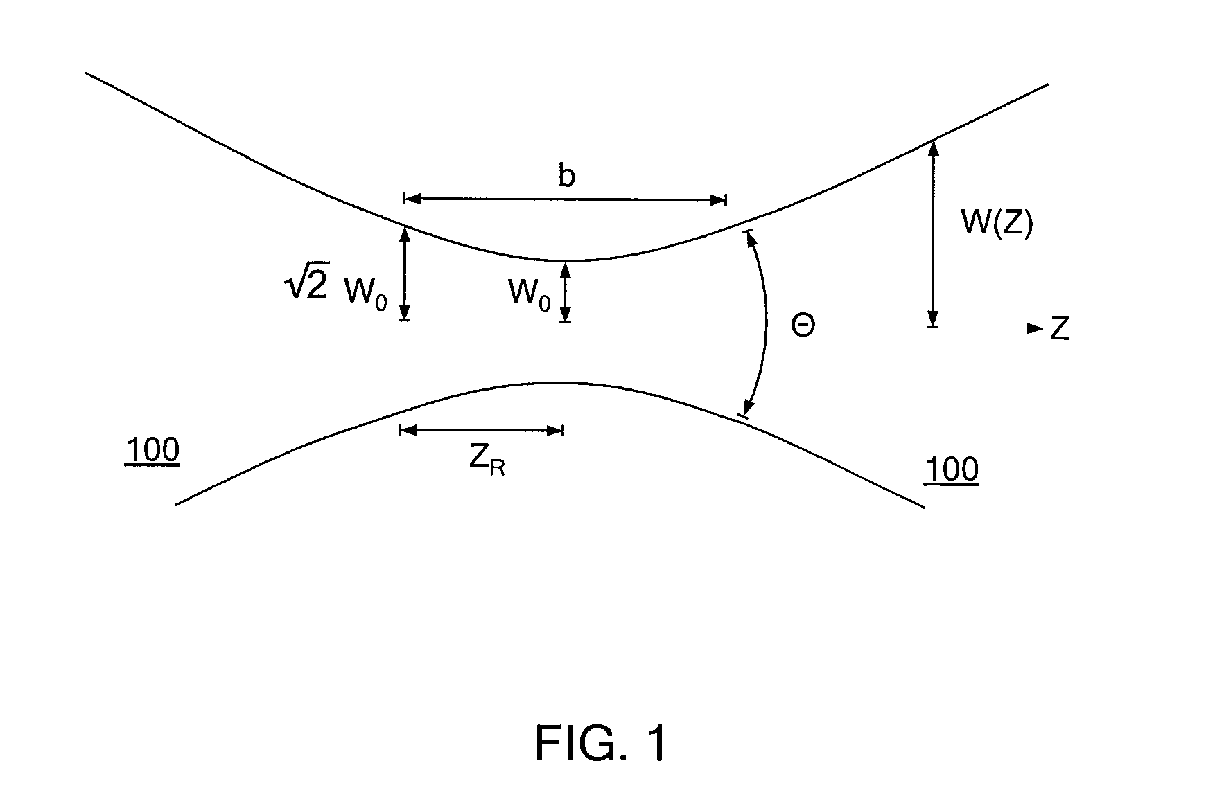
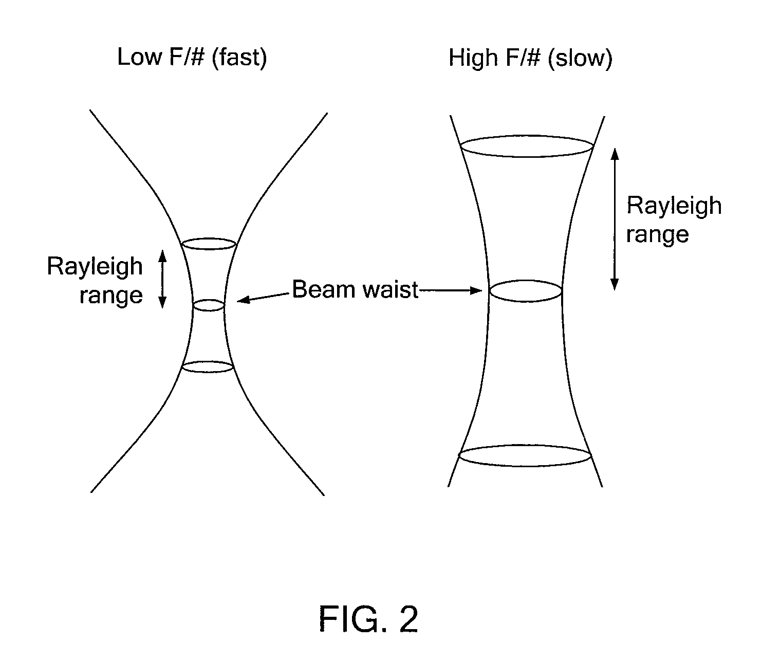
[0046]Note that in order to understand some of the properties of the present invention, FIG. 1 is presented which schematically shows a beam, such as a Gaussian beam 100. The beam waist Wo and Rayleigh range ZR are two key parameters that determine how localized the photodisruption and additional thermal effects will be around the focal point of the beam. The beam waist is directly proportional to the beam F / #, so the peak spatial irradiance at the waist is inversely proportional to the square of the F / #. The Rayleigh range of a Gaussian beam is defined as the distance along the laser beam (Z-axis) from the beam waist to the point where the beam expands by sqrt(2), and is directly proportional to the square of the beam waist. Therefore, the Rayleigh range is inversely proportional to the square of the F / #. Note that at one Rayleigh range away from the waist, the peak irradiance will drop in half compared to the peak irradiance at the waist. With the above said, the Rayleigh range an...


PUM


Abstract

A laser system including a laser source that generates a laser beam and an optical switch that receives the laser beam and sends the laser beam to either a fast path or a slow path, wherein the F/# of the fast path is lower than the F/# of the slow path. The laser system includes an afocal optical system in the slow path and receives the laser beam from the optical switch and an x-y scanner that receives either a laser beam from the slow path or a laser beam from the fast path. The laser system including a scan lens system that performs a z-scan for the scanning laser beam only in the case wherein the scanning laser beam is generated from the laser beam in the fast path. The laser system including an aspheric patient interface device that receives a laser beam from the scan lens system.

Description

[0001]This application claims the benefit of priority under 35 U.S.C. §119(e)(1) of 1) U.S. Provisional Application Ser. No. 61 / 470,734, filed Apr. 1, 2011 and 2) U.S. Provisional Application Ser. No. 61 / 550,101, filed Oct. 21, 2011, the entire contents of each of which is incorporated herein by reference.FIELD OF THE INVENTION[0002]The present invention relates to a system and method for laser generated corneal and crystalline lens incisions.BACKGROUND[0003]Recently, femtosecond laser systems are emerging as an alternative to manual incisions in the cornea and crystalline lens for different ophthalmic surgeries. Examples of such laser systems are the Intralase FS Laser and IFS Advanced Femtosecond Laser manufactured and sold by Abbott Medical Optics of Abbott Park, Ill. and the LenSx Femtosecond Laser manufactured and sold by LenSx Lasers of Aliso Viejo, Calif. Such lasers make incisions by focusing ultrashort laser pulses to a very fine focus, causing a plasma mediated photodisrup...

Claims


Application Information

Patent Timeline
IPC IPC(8): G02B26/10A61F9/009G02B5/30A61F9/01G02B13/00G02B27/10
CPCA61F9/00825A61F2009/0087A61F2009/00872G02B27/0031G02B13/0005G02B15/177G02B26/101A61F2009/00897A61F9/009
Inventor CURATU, GEORGE C.FREY, RUDOLPH W.MCWHIRTER, JOHNBOTT, STEVEN E.
Owner LENSAR LLC
Why Eureka
Try Eureka