

Image relay optical system and virtual image display device including the same
- Summary
- Abstract
- Description
- Claims
- Application Information
AI Technical Summary
Benefits of technology
Problems solved by technology
Method used
Image

Examples
first embodiment
[0026]An image relay optical system for a virtual image display device and a virtual image display device incorporating the image relay optical system according to a first embodiment of the invention are explained below with reference to the accompanying drawings.
A. Structure of the Image Relay Optical System and the Virtual Image Display Device
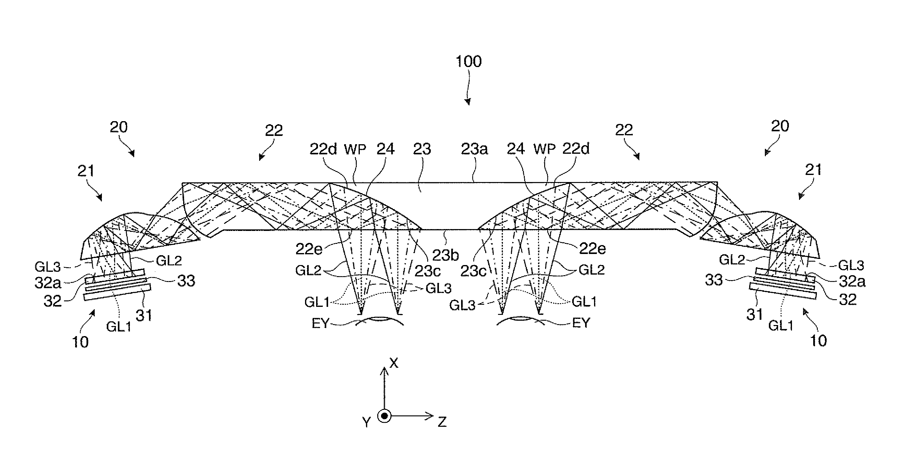
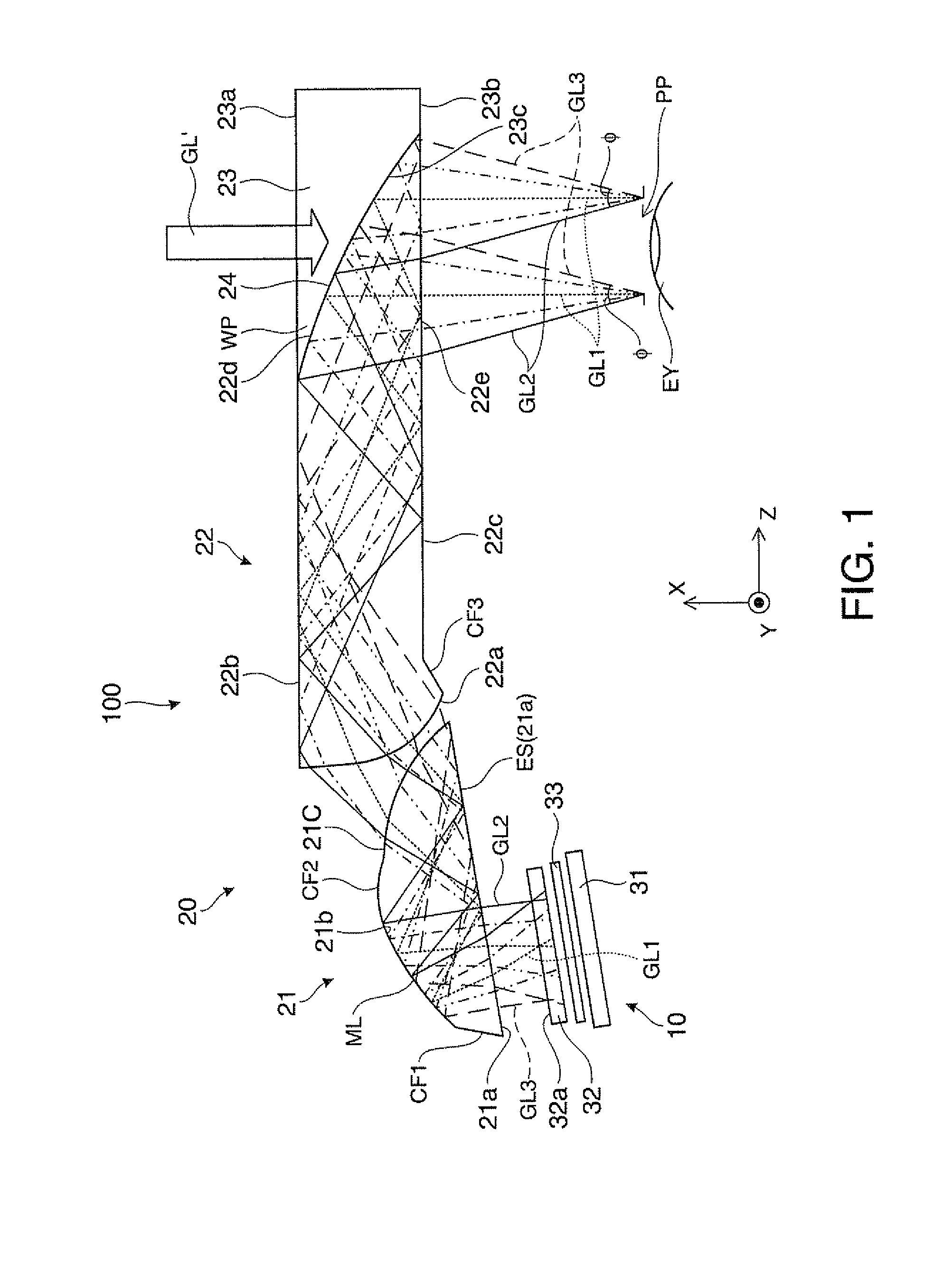
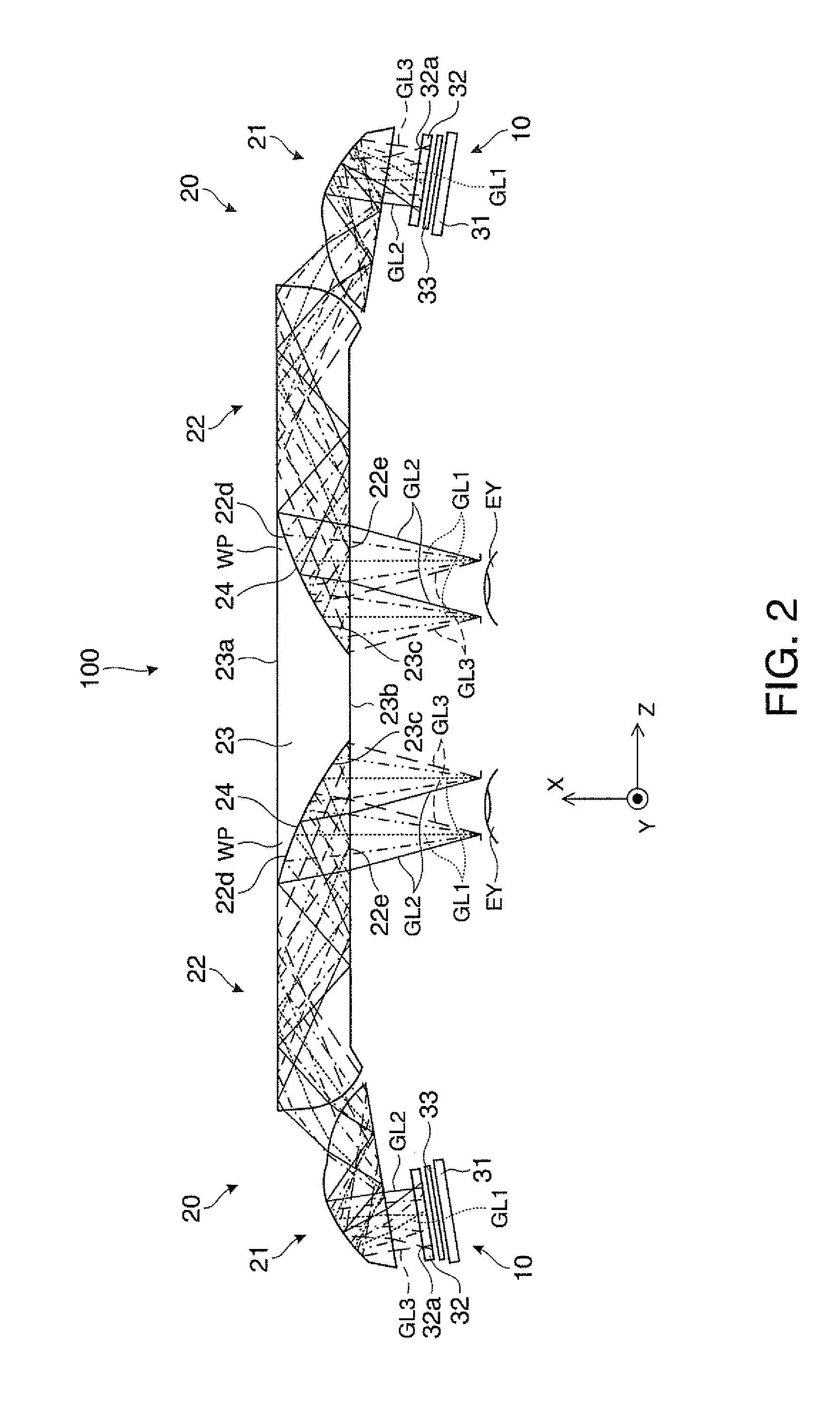
[0027]A virtual image display device 100 according to this embodiment shown in FIG. 1 is applied to a head mounted display and includes an image forming device 10 and an image relay optical system 20 as a set.
[0028]The virtual image display device 100 causes an observer to recognize image lights generated by a virtual image and causes the observer to observe an external image in a see-through manner. FIG. 1 shows only the virtual image display device 100 for the left eye. However, as the entire virtual image display device 100, the set of the image forming device 10 and the image relay optical system 201 provided to correspond to each of the ...
second embodiment
[0045]A second embodiment obtained by modifying the first embodiment is explained below with reference to FIG. 4. An image relay optical system and a virtual image display device according to this embodiment have structure same as the structure shown in FIG. 1 except the optical coupling member 21 and the light guide member 22. Therefore, explanation is omitted concerning components serving as functional components of the image forming device 10 and the like. The light transmitting member is not shown in the figure.
[0046]As shown in FIG. 4, in this embodiment, in the optical coupling member 21 of the image relay optical system 20, the first light incident surface 21a is a convex convergent surface (specifically, a convex spherical surface or aspherical surface), the coupling member reflecting surface 21b is a concave convergent surface (specifically, a concave spherical surface or aspherical surface), and the first light emitting surface 21c is a convex convergent surface (specifica...
third embodiment
[0051]A third embodiment obtained by modifying the first embodiment is explained below with reference to FIG. 5. An image relay optical system and a virtual image display device according to this embodiment have structure same as the structure shown in FIG. 1 except the section from the optical coupling member 21 to the light guide member 22. Therefore, explanation is omitted concerning components serving as functional components of the image forming device 10 and the like. The light transmitting member is not shown in the figure.
[0052]As shown in FIG. 5, in this embodiment, in the optical coupling member 21 of the image relay optical system 20, the first light incident surface 21a is a convex convergent surface (specifically, a convex spherical surface or aspherical surface), the coupling member reflecting surface 21b is a concave convergent surface (specifically, a concave spherical surface or aspherical surface), and the first light emitting surface 21c is a convex convergent sur...
PUM
 Abstract
Description
Claims
Application Information