Image-forming optical system

a technology of optical systems and optical components, applied in the field of image-forming optical systems, can solve the problems of limiting the reduction in the thickness of the optical system, the increase in the number of lens elements, and the difficulty in reducing the cost in the present state of the art, so as to achieve the reduction of aberrations, the degree of design freedom is increased, and the degree of freedom for aberration correction is increased.

Inactive Publication Date: 2009-04-28
OLYMPUS CORP
View PDF13 Cites 0 Cited by
  • Summary
  • Abstract
  • Description
  • Claims
  • Application Information

AI Technical Summary

Benefits of technology

[0062]In the present invention, the prism object-side part and the prism image-side part may be made of different materials and cemented together. Alternatively, the prism object-side part and the prism image-side part may be placed adjacently to each other with a small spacing therebetween. In either case, the advantageous effects of the present invention can be obtained satisfactorily.
[0063]Incidentally, it is desirable to arrange the prism optical system such that the two reflecting surfaces C and B, which are placed in the image-side part of the prism optical system, are positioned to face each other across the prism medium, and the surface A, which has a transmitting action by which a light beam is allowed to exit from the prism, is disposed between the surfaces C and B, thereby forming a Z-shaped optical path.
[0064]As stated above, the surfaces A to C in the prism image-side part are arranged to form a Z-shaped optical path in the prism. In other words, the surfaces A to C are arranged such that optical paths in the prism do not intersect each other. With the above-described arrangement, directions in which the axial principal ray is incident on and reflected from the surface C, respectively, are opposite to directions in which the axial principal ray are incident on and reflected from the surface B. Accordingly, it is easy to correct the optical system for aberrations, and the arrangement is favorable from the viewpoint of design and aberration correcting performance.
[0065]By arranging the prism image-side part as stated above, the angle of reflection in the prism image-side part can be made gentle in comparison to a prism structure in which the entrance position to the prism image-side part and the exit surface are adjacent to each other. Accordingly, the aggravation of aberrations is reduced, and the degree of design freedom increases.
[0066]If the prism image-side part is constructed by using two reflecting surfaces and one transmitting surface as stated above, the degree of freedom for aberration correction increases, and the amount of aberration produced in the prism image-side part is favorably small. In addition, because the relative decentration between the two reflecting surfaces is small, aberrations produced by the two reflecting surfaces are corrected with these reflecting surfaces by canceling the aberrations each other. Therefore, the amount of aberration produced in the prism is favorably small. It is more desirable that the two reflecting surfaces should have powers of different signs. By doing so, it is possible to enhance the effect of correcting each other's aberrations by the two reflecting surfaces and hence possible to obtain high resolution.
[0067]It is preferable to minimize the relative decentration between the surfaces C and B at the respective positions where the optical axis is reflected. By doing so, it is possible to minimize the amount of decentration aberrations. Thus, the amount of rotationally asymmetric aberrations produced in the prism becomes small.

Problems solved by technology

Therefore, there is a limit to the reduction in thickness of the optical systems.
At the same time, the number of lens elements unavoidably increases because it is necessary to correct chromatic aberration produced by a rotationally symmetric refracting lens used in the optical systems.
Therefore, it is difficult to reduce the cost in the present state of the art.
In an example thereof, however, the number of constituent optical members is as large as five, and actual optical performance is unclear.
Accordingly, surface accuracy errors and decentration accuracy errors are transferred while being added up.
Consequently, the accuracy required for each surface becomes tight, causing the cost to increase unfavorably.
The relay of the image also causes the overall volumetric capacity of the optical system to increase unfavorably.
However, because the optical system is arranged to relay an image, the cost increases and the optical system becomes large in size unfavorably for the same reasons as stated above.
However, the optical system is not satisfactorily corrected for aberrations.
In these examples, however, the number of reflections is undesirably large because an image is relayed in a prism.
Therefore, surface accuracy errors and decentration accuracy errors of reflecting surfaces are transferred while being added up, unfavorably.
At the same time, the overall size of the optical system unavoidably increases, unfavorably.
Accordingly, the prisms themselves become unavoidably large in size.
Furthermore, because the disclosed zoom lens systems are not telecentric on the image side, it is difficult to apply them to image pickup devices such as CCDs.
Accordingly, the decentration accuracy required for the reflecting surfaces becomes tight in order to maintain the required performance over the entire zooming range, resulting in an increase in the cost.
To correct the chromatic aberration and also correct other ray aberrations, the refracting optical system needs a large number of constituent elements, causing the cost to increase.
In addition, because the optical path extends straight along the optical axis, the entire optical system undesirably lengthens in the direction of the optical axis, resulting in an unfavorably large-sized image pickup apparatus.
In decentered optical systems such as those described above in regard to the prior-art, an imaged figure or the like is undesirably distorted and the correct shape cannot be reproduced unless the formed image is favorably corrected for aberrations, particularly rotationally asymmetric distortion.
Furthermore, in a case where a reflecting surface is used in a decentered optical system, the sensitivity to decentration errors of the reflecting surface is twice as high as that in the case of a refracting surface, and as the number of reflections increases, decentration errors that are transferred while being added up increase correspondingly.
Consequently, manufacturing accuracy and assembly accuracy, e.g. surface accuracy and decentration accuracy, required for reflecting surfaces become even more strict.

Method used


Image

  • Image-forming optical system
  • Image-forming optical system
  • Image-forming optical system

Examples


examples 1 and 7

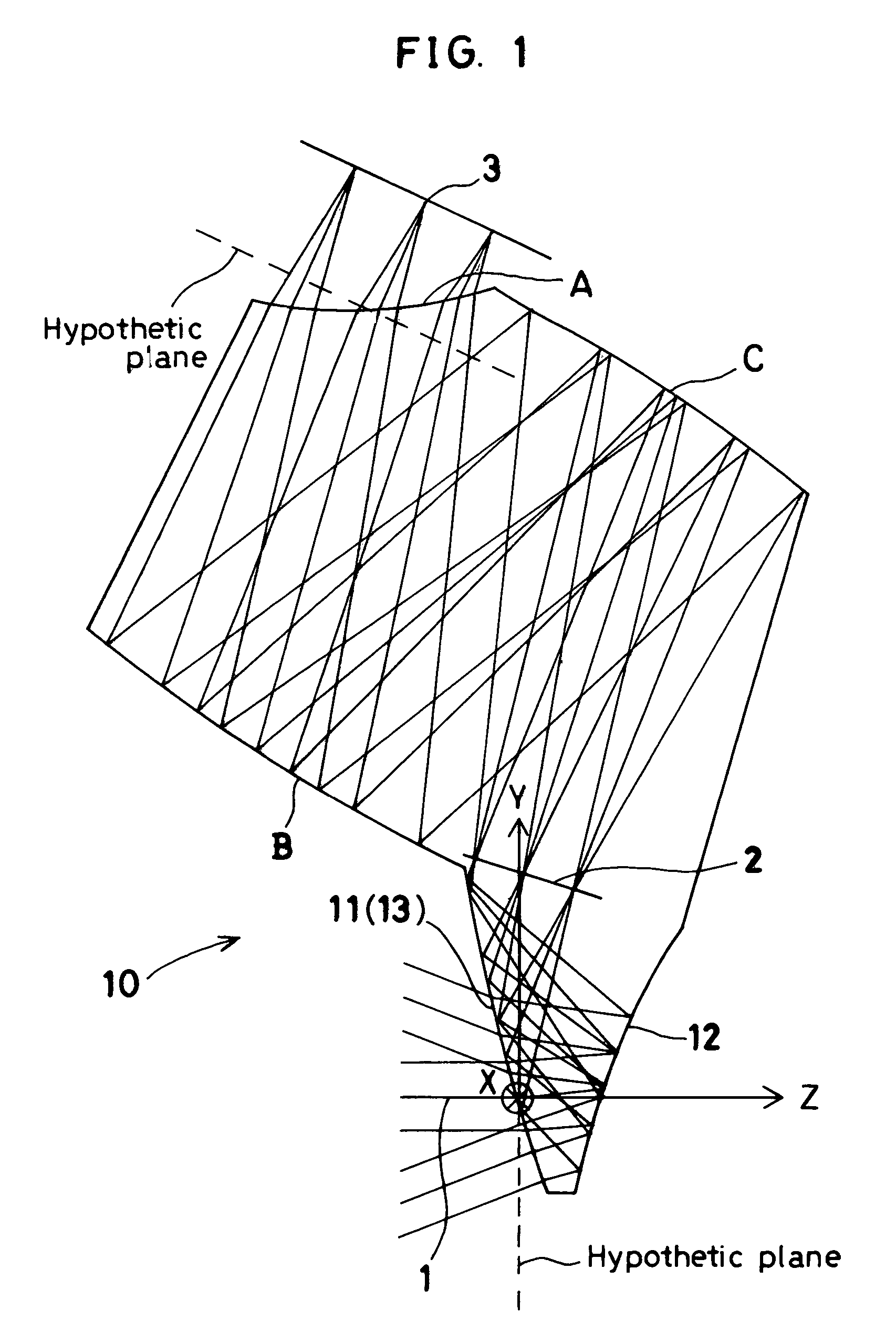
[0203]FIG. 1 is a sectional view of Example 1 taken along the YZ-plane containing the axial principal ray. The sectional view of Example 7 is similar to FIG. 1. Therefore, illustration of Example 7 is omitted. Constituent parameters of these examples will be shown later. In the constituent parameters, free-form surfaces are denoted by “FFS”, and hypothetic planes by “HRP” (Hypothetic Reference Plane). The same shall apply to the other examples.

[0204]Examples 1 and 7 each have, in order in which light passes from the object side, an object-side part of a prism 10, a stop 2, an image-side part of the prism 10, and an image plane (image-formation plane) 3. The object-side part of the prism 10 comprises an entrance surface 11 as a first surface, a first reflecting surface 12, and a second reflecting surface 13 formed from the first surface 11, which also serves as the entrance surface 11. The image-side part of the prism 10 comprises a surface C as a third reflecting surface, a surface ...

examples 2 and 8

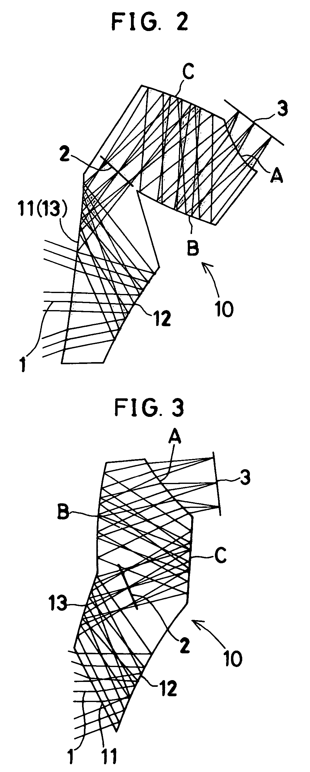
[0206]FIG. 2 is a sectional view of Example 2 taken along the YZ-plane containing the axial principal ray. The sectional view of Example 8 is similar to FIG. 2. Therefore, illustration of Example 8 is omitted. Constituent parameters of these examples will be shown later.

[0207]Examples 2 and 8 each have, in order in which light passes from the object side, an object-side part of a prism 10, a stop 2, an image-side part of the prism 10, and an image plane (image-formation plane) 3. The object-side part of the prism 10 comprises an entrance surface 11 as a first surface, a first reflecting surface 12, and a second reflecting surface 13 formed from the first surface 11, which also serves as the entrance surface 11. The image-side part of the prism 10 comprises a surface C as a third reflecting surface, a surface B as a fourth reflecting surface, and a surface A as an exit surface. Rays from an object enter through the entrance surface 11 and are reflected successively by the first refle...

examples 3 and 9

[0209]FIG. 3 is a sectional view of Example 3 taken along the Y-Z-plane containing the axial principal ray. The sectional view of Example 9 is similar to FIG. 3. Therefore, illustration of Example 9 is omitted. Constituent parameters of these examples will be shown later.

[0210]Examples 3 and 9 each have, in order in which light passes from the object side, an object-side part of a prism 10, a stop 2, an image-side part of the prism 10, and an image plane (image-formation plane) 3. The object-side part of the prism 10 comprises an entrance surface 11 as a first surface, a first reflecting surface 12, and a second reflecting surface 13. The image-side part of the prism 10 comprises a surface C as a third reflecting surface, a surface B as a fourth reflecting surface, and a surface A as an exit surface. Rays from an object enter through the entrance surface 11 and are reflected successively by the first reflecting surface 12 and the second reflecting surface 13. Then, the rays pass thr...


PUM


Abstract

A high-performance image-forming optical system made compact and thin by folding an optical path using reflecting surfaces arranged to minimize the number of reflections. The image-forming optical system has a single prism. When image-side three surfaces of the prism are defined as a surface A, a surface B and a surface C in order from the image plane side thereof, at least one of the surfaces B and C has a rotationally asymmetric curved surface configuration that gives a power to a light beam and corrects aberrations due to decentration. The optical system leads light rays from an object to the image plane without forming an image in the prism and has a pupil in the prism. The surface A is a transmitting surface through which rays exit from the prism. The surfaces B and C are internally reflecting surfaces, which are positioned to face each other to form a Z-shaped optical path.

Description

[0001]This is a continuation of U.S. application Ser. No. 09 / 417,914, file Oct. 13, 1999 now U.S. Pat. No. 6,788,343, the contents of which are incorporated herein by reference in their entirety.BACKGROUND OF THE INVENTION[0002]The present invention relates to image-forming optical systems. More particularly, the present invention relates to a decentered optical system with a reflecting surface having a power for use in optical apparatus using digital still cameras, film scanners, and endoscopes. a small-sized image pickup device, e.g. video cameras,[0003]Recently, with the achievement of small-sized image pickup devices, image-forming optical systems for use in video cameras, digital still cameras, film scanners, endoscopes, etc. have also been demanded to be reduced in size and weight and also in cost.[0004]In the general rotationally symmetric coaxial optical systems, however, optical elements are arranged in the direction of the optical axis. Therefore, there is a limit to the r...

Claims


Application Information

Patent Timeline
Patent Type & Authority Patents(United States)
IPC IPC(8): G03B21/14G02B17/08H04N5/225H04N5/232
CPCG02B17/0848G02B17/086H04N5/2254H04N5/23293H04N2005/2255H04N23/555H04N23/55H04N23/63
Inventor TOGINO, TAKAYOSHI
Owner OLYMPUS CORP
Why Eureka
Try Eureka