Zoom lens, imaging device and method for manufacturing the zoom lens

a technology of zoom lens and imaging device, which is applied in the field of zoom lens, imaging device and method for manufacturing the zoom lens, can solve the problems of insufficient miniaturization of conventional zoom lens, increase in the size of the zoom lens, etc., and achieve the effect of low aberration and high performan

Active Publication Date: 2016-05-17
NIKON CORP
View PDF29 Cites 0 Cited by
  • Summary
  • Abstract
  • Description
  • Claims
  • Application Information

AI Technical Summary

Benefits of technology

[0018]According to the present invention, a zoom lens which is miniaturized, constituted by a small number of lenses, has high performance and little aberrations, an imaging device including this zoom lens, and a method for manufacturing this zoom lens can be provided.

Problems solved by technology

Conventional zoom lenses, however, are insufficient in terms of miniaturization.
If refractive power of each lens group is increased in order to implement miniaturization and higher performance, lens configuration becomes complicated because of the necessity of correcting aberrations and the number of constituting lenses increases, resulting in an increase in the size of the zoom lens, which is the opposite of the intention.

Method used


Image

  • Zoom lens, imaging device and method for manufacturing the zoom lens
  • Zoom lens, imaging device and method for manufacturing the zoom lens
  • Zoom lens, imaging device and method for manufacturing the zoom lens

Examples


example 1

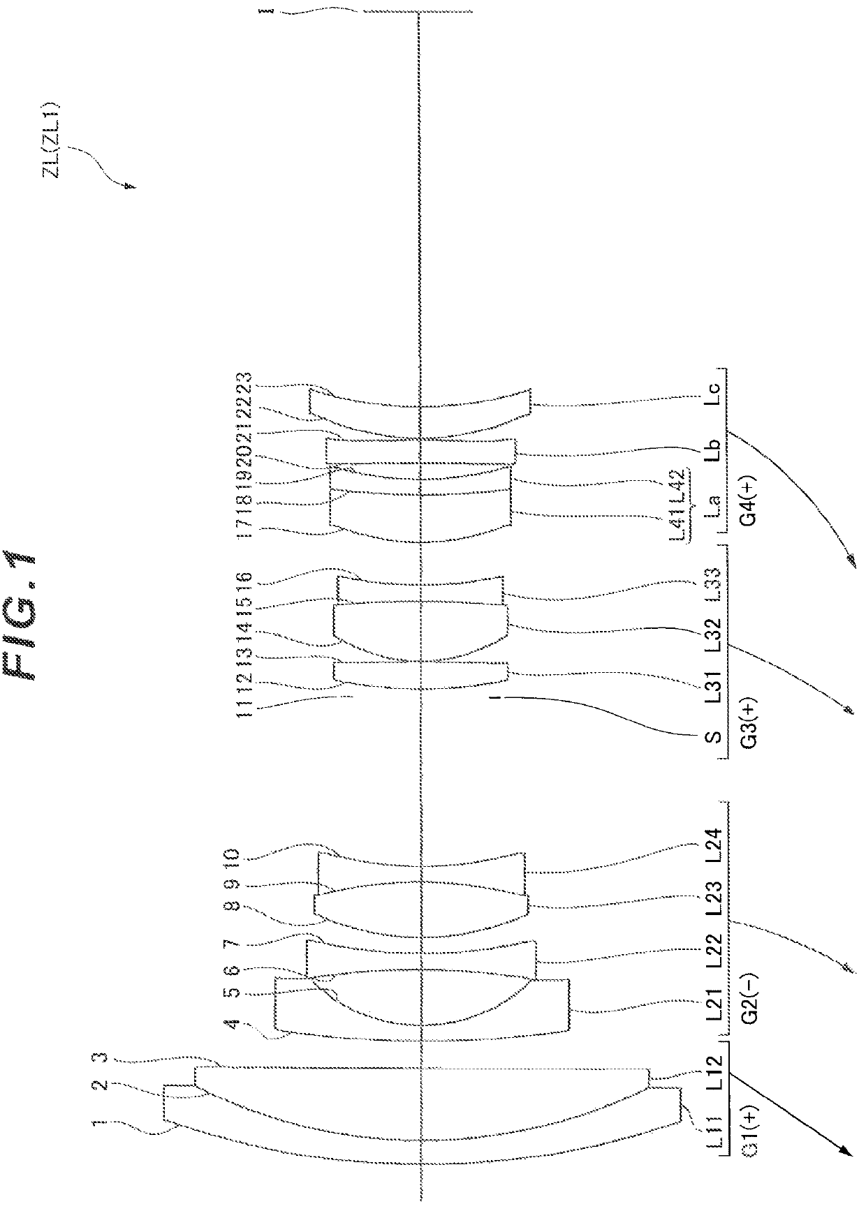
[0089]Example 1 will be described with reference to FIG. 1, FIG. 2 and Table 1. FIG. 1 shows a configuration of a zoom lens ZL (ZL1) according to Example 1 and a zoom track from the wide-angle end state (W) to a telephoto end state (T). As FIG. 1 shows, the zoom lens ZL1 according to Example 1 includes, in order from the object: a first lens group G1 having positive refractive power; a second lens group G2 having negative refractive power; a third lens group G3 having positive refractive power; and a fourth lens group G4 having positive refractive power, wherein zooming is performed by changing an air gap between the lens groups.

[0090]The first lens group G1 is configured of a cemented positive lens in which a negative meniscus lens L11 having a convex surface facing the object and a positive meniscus lens L12 are cemented in order from the object.

[0091]The second lens group G2 is configured of, in order from the object, a negative meniscus aspherical lens L21 having a convex surfac...

example 2

[0100]Example 2 will be described with reference to FIG. 3, FIG. 4 and Table 2. FIG. 3 shows a configuration of a zoom lens ZL (ZL2) according to Example 2, and a zoom track from wide-angle end state (W) to a telephoto end state (T). As FIG. 3 shows, the zoom lens ZL2 according to Example 2 includes, in order from an object: a first lens group G1 having positive refractive power; a second lens group G2 having negative refractive power; a third lens group G3 having positive refractive power; and a fourth lens group G4 having positive refractive power, wherein zooming is performed by changing an air gap between the lens groups.

[0101]The first lens group G1 is configured of a cemented positive lens in which a negative meniscus lens L11 having a convex surface facing the object and a positive meniscus lens L12 are cemented in order from the object.

[0102]The second lens group G2 is configured of, in order from the object, a negative meniscus aspherical lens 121 having a convex surface fa...


PUM

PropertyMeasurementUnit
refractive poweraaaaaaaaaa
radius of curvatureaaaaaaaaaa
focal lengthaaaaaaaaaa

Abstract

A zoom lens has, in order from an object, a first lens group (G1) having positive refractive power; a second lens group (G2) having negative refractive power; a third lens group (G3) having positive refractive power; and a fourth lens group (G4) having positive refractive power. Zooming is performed by changing an air gap between the lens groups. The fourth lens group (G4) includes, in order from the object, a lens component (La) having positive or negative refractive power, a positive lens component (Lb), and a positive lens component (Lc) having a convex surface facing the object. Specified conditional expressions are satisfied.

Description

TECHNICAL FIELD[0001]The present invention relates to a zoom lens, an imaging device and a method for manufacturing the zoom lens.TECHNICAL BACKGROUND[0002]A miniaturized zoom lens has been conventionally proposed (e.g. see Patent Document 1).PRIOR ARTS LISTPatent Document[0003]Patent Document 1: Japanese Laid-Open Patent Publication No. H3-29912(A)[0004]Conventional zoom lenses, however, are insufficient in terms of miniaturization. If refractive power of each lens group is increased in order to implement miniaturization and higher performance, lens configuration becomes complicated because of the necessity of correcting aberrations and the number of constituting lenses increases, resulting in an increase in the size of the zoom lens, which is the opposite of the intention.SUMMARY OF THE INVENTIONProblems to be Solved by the Invention[0005]With the foregoing in view, it is an object of the present invention to provide a zoom lens which is miniaturized, constituted by a small number...

Claims


Application Information

Patent Timeline
Patent Type & Authority Patents(United States)
IPC IPC(8): G02B15/14G02B9/34G02B13/18G02B15/173
CPCG02B9/34G02B13/18G02B15/173G02B15/14Y10T29/49826G02B15/144113
Inventor SATO, HARUO
Owner NIKON CORP
Why Eureka
Try Eureka