Image reading apparatus and image reading method

Inactive Publication Date: 2005-06-23
HITACHI SOFTWARE ENG
View PDF11 Cites 0 Cited by
  • Summary
  • Abstract
  • Description
  • Claims
  • Application Information

AI Technical Summary

Benefits of technology

[0017] According to the present invention, a high resolution or low noise image can be obtained without having the difference of brightness in the peripheral portions of the imaging range as compared with the method for imaging the entire area of a slide gla

Problems solved by technology

Meanwhile, it may pose problems upon synthesizing the divided images.
Specifically, the joints of images have different brightness when the images are synthesized if uniform fluorescence intensity cannot be obtained in the entire imaging area due to the unevenness of excitation light.
Also, a portion of the image is duplicated or lost when the images are synthesized, since distortion is generated in the images due to the aberration of a lens.
Further, when detecting

Method used


Image

  • Image reading apparatus and image reading method
  • Image reading apparatus and image reading method
  • Image reading apparatus and image reading method

Examples


Example

[0028] In the following, embodiment of the present invention is described with reference to the drawings.

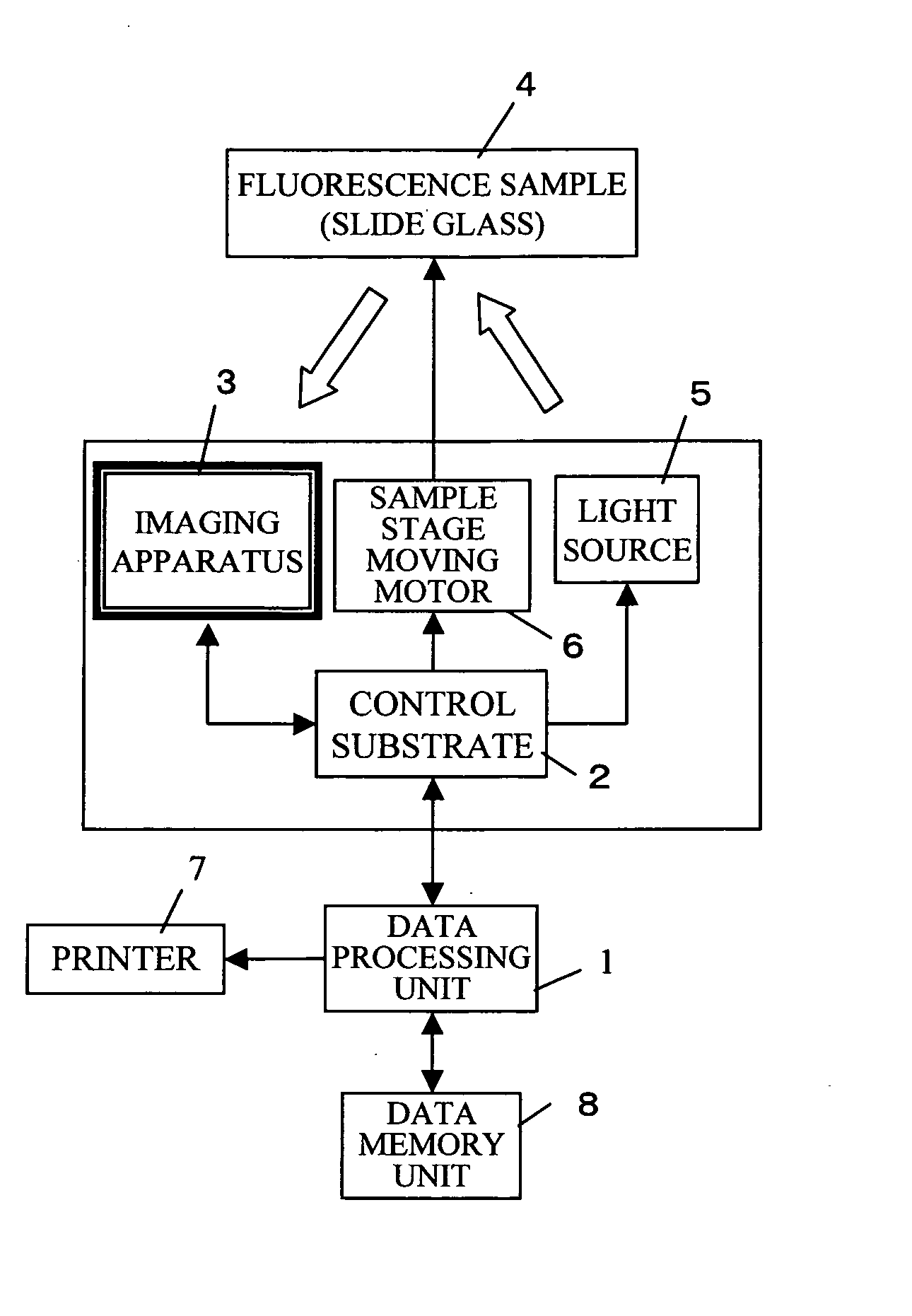
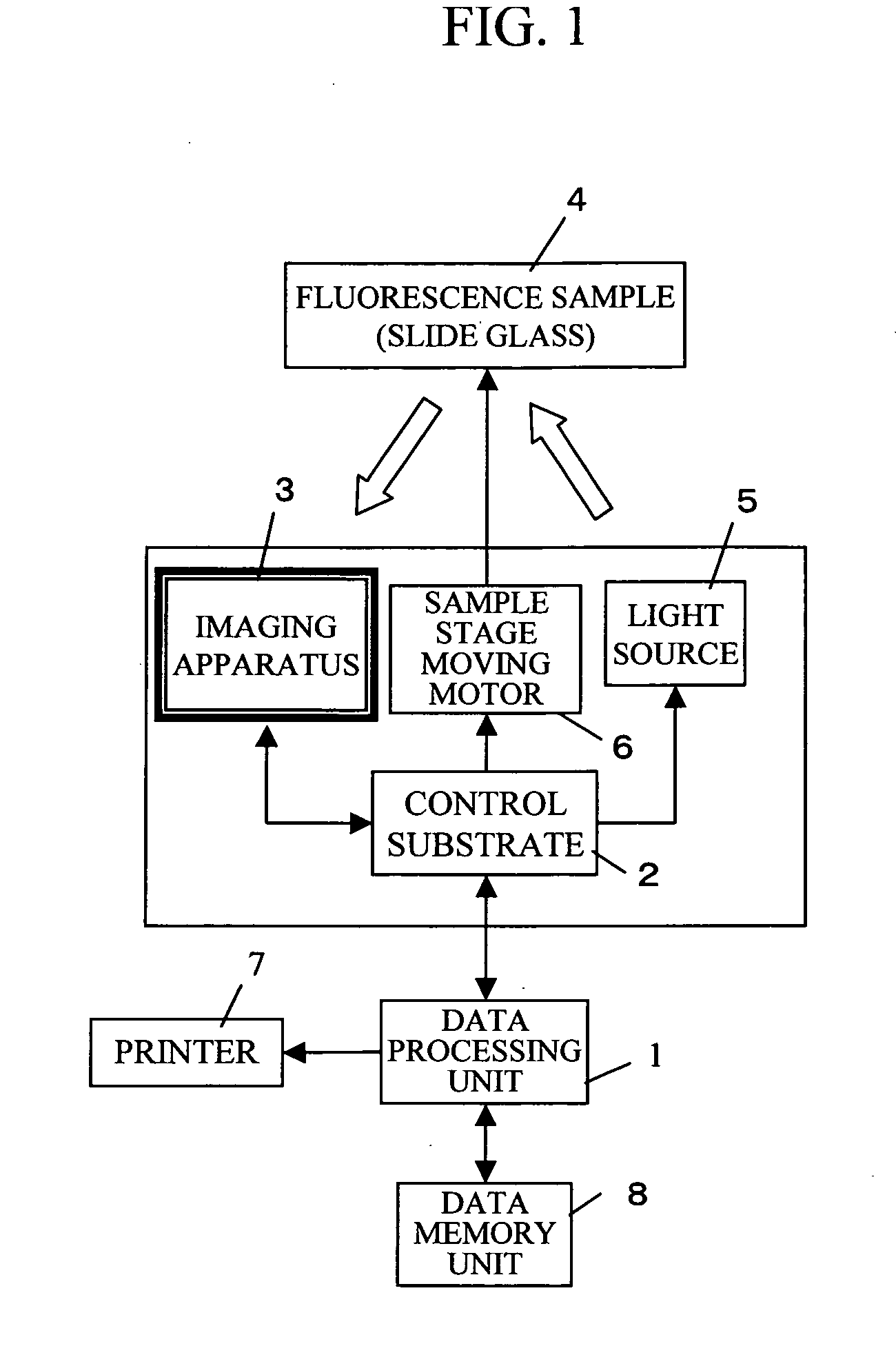
[0029]FIG. 1 shows a block diagram of the outline example of the image reading apparatus according to the present invention. Excitation light emitted from a light source 5 is irradiated onto a sample (slide glass) 4. Fluorescence from the sample 4 is detected by a two-dimensional imaging apparatus 3 such as a CCD, and then converted into an electric signal to be transferred to a control substrate 2. A sample stage that supports the sample 4 is moved on a reading position by a sample stage moving motor 6. In the present embodiment, a stepping motor is employed for the sample stage moving motor 6. The sample stage moving motor 6 is controlled by the control substrate 2 and the control substrate 2 is controlled by a data processing unit 1. The data processing unit 1 is connected to a data memory unit 8 and processed data can be stored in the data memory unit 8. Also, the data proce...


PUM


Abstract

Sensitivity error, image distortion, and background noise upon synthesizing images obtained by an imaging apparatus, and lack of resolution upon reading the entire area of a sample at a time are solved. While moving the sample by the distance that corresponds to the resolution, the sample is read using all the scanning lines of the imaging apparatus, and then an entire image is obtained by synthesizing each line. The imaging apparatus is located such that the scanning lines are parallel to the short side of the sample, and the short side direction is resolved by the maximum resolution of the imaging apparatus.

Description

BACKGROUND OF THE INVENTION [0001] 1. Field of the Invention [0002] The present invention relates to an image reading apparatus and an image reading method, and to an image reading apparatus and an image reading method that are suitable for reading a fluorescent-labeled sample. [0003] 2. Background Art [0004] As imaging methods when reading fluorescence of a microarray by a CCD sensor after a hybridization reaction, there are a method by which the entire area of the microarray is put into one visual field for reading, and a method by which the microarray is divided for reading and an image is synthesized afterward. In the former case, the maximum resolution upon imaging is limited in accordance with the length of a diagonal line of the microarray, since the diagonal line of the microarray must be within the imaging range of the CCD sensor. In the latter case, higher resolution can be obtained, since smaller ranges of the microarray are put into the imaging range of the CCD sensor. [...

Claims


Application Information

Patent Timeline
IPC IPC(8): G02B21/00G02B21/36G01N21/64H04N1/10H04N1/12H04N1/195
CPCH04N1/12H04N1/1915H04N1/195H04N2201/04793H04N5/349H04N5/35572H04N2201/04737H04N1/19521H04N25/48H04N25/587
Inventor OISHI, TAKESHI
Owner HITACHI SOFTWARE ENG
Why Eureka
Try Eureka