3D television system and method

a 3d tv and system technology, applied in the field of image processing, can solve the problems of not fully functional end-to-end 3d tv system implementation, inability to acquire dynamic lightfields only recently, and inherently require high resolution of imaging medium, etc., to achieve high resolution, high scalability, and high resolution. , the effect of high resolution

Inactive Publication Date: 2005-08-25
MITSUBISHI ELECTRIC RES LAB INC
View PDF4 Cites 335 Cited by
  • Summary
  • Abstract
  • Description
  • Claims
  • Application Information

AI Technical Summary

Benefits of technology

[0054] Scalable multi-projector display walls have recently become popular, and many systems have been implemented, e.g., Raskar et al., “The office of the future: A unified approach to image-based modeling and spatially immersive displays,”Proceedings of SIGGRAPH '98, pp. 179-188, 1998. Those systems offer very high resolution, flexibility, excellent cost-performance, scalability, and large-format images. Graphics rendering for multi-projector systems can be efficiently parallelized on clusters of PCs.
[0055] Projectors also provide the necessary flexibility to adapt to non-planar display geometries. For large displays, multi-projector systems remain the only choice for multi-view 3D displays until very high-resolution display media, e.g., organic LEDs, become available. However, manual alignment of many projectors becomes tedious, and downright impossible in the case of non-planar screens or 3D multi-view displays.

Problems solved by technology

However, the simultaneous display of multiple perspective views inherently requires a very high resolution of the imaging medium.
However, so far, no fully functional end-to-end 3D TV system has been implemented.
Acquisition of dynamic lightfields has only recently become feasible, Naemura et al.
Blue-C uses a centralized processor for the compression and transmission of 3D “video fragments.” This limits the scalability of that system with an increasing number of views.
However, even with accurate depth maps, it is difficult to render multiple high-quality views on the display side because of occlusions or high disparity in the scene.
Moreover, a single video stream cannot capture important view-dependent effects, such as specular highlights.
Real-time acquisition of depth or geometry for real-world scenes remains very difficult.
However, very little attention has been paid to the compression and transmission of dynamic lightfields.
This leads to a reduced transmission bandwidth, but that encoding is not amenable for 3D TV broadcasting.
The acquisition of holograms still demands carefully controlled physical processes and cannot be done in real-time.
However, volumetric systems produce transparent images that do not provide a fully convincing three-dimensional experience.
Because of their limited color reproduction and lack of occlusions, volumetric displays cannot correctly reproduce the lightfield of a natural scene.
The design of large-size volumetric displays also poses some difficult obstacles.
The number of distinct perspective views is generally limited.
This inherently reduces the frame rate of the display and can lead to noticeable flickering.
However, manual alignment of many projectors becomes tedious, and downright impossible in the case of non-planar screens or 3D multi-view displays.

Method used


Image

  • 3D television system and method
  • 3D television system and method
  • 3D television system and method

Examples


Embodiment Construction

[0065] System Architecture

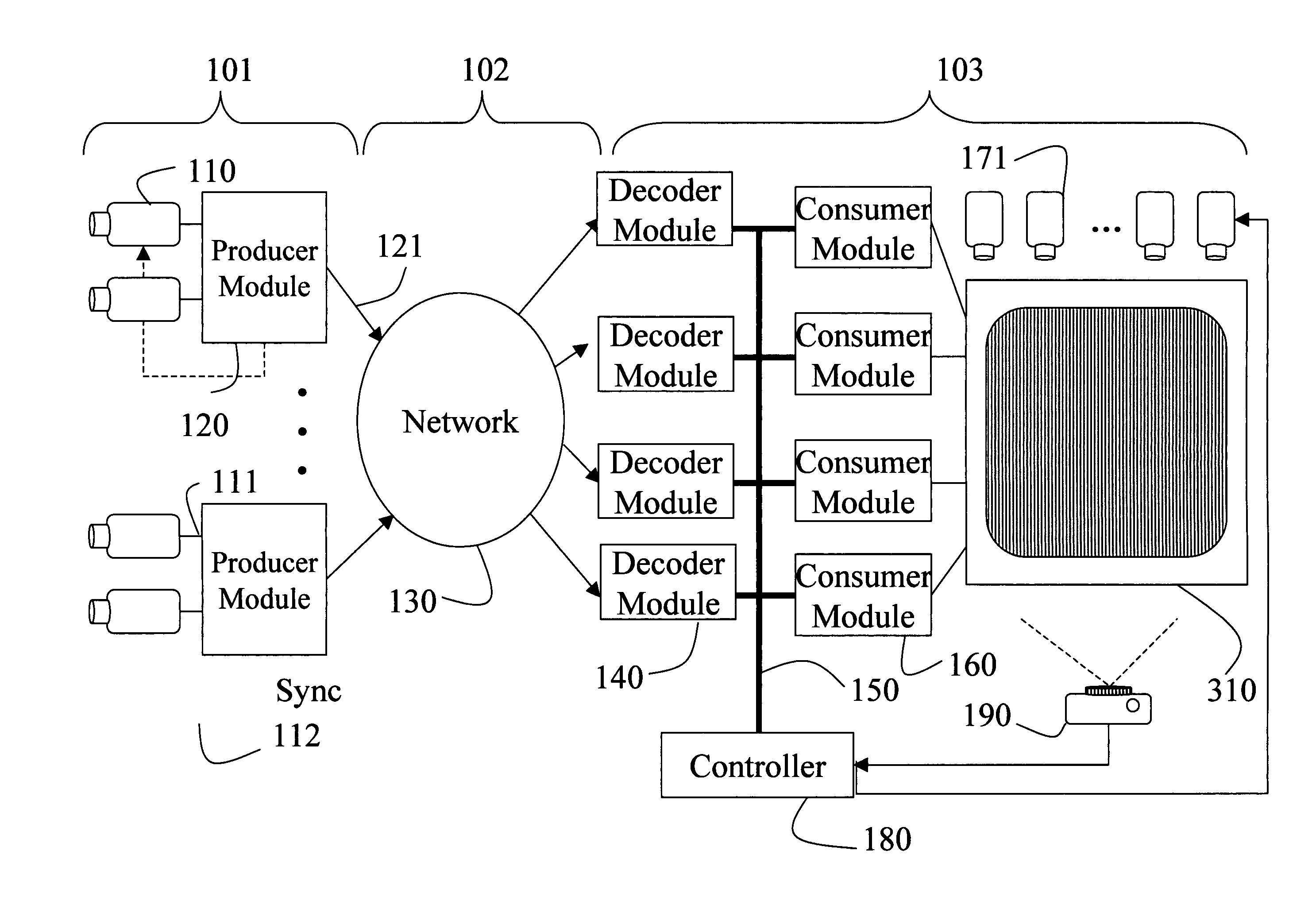
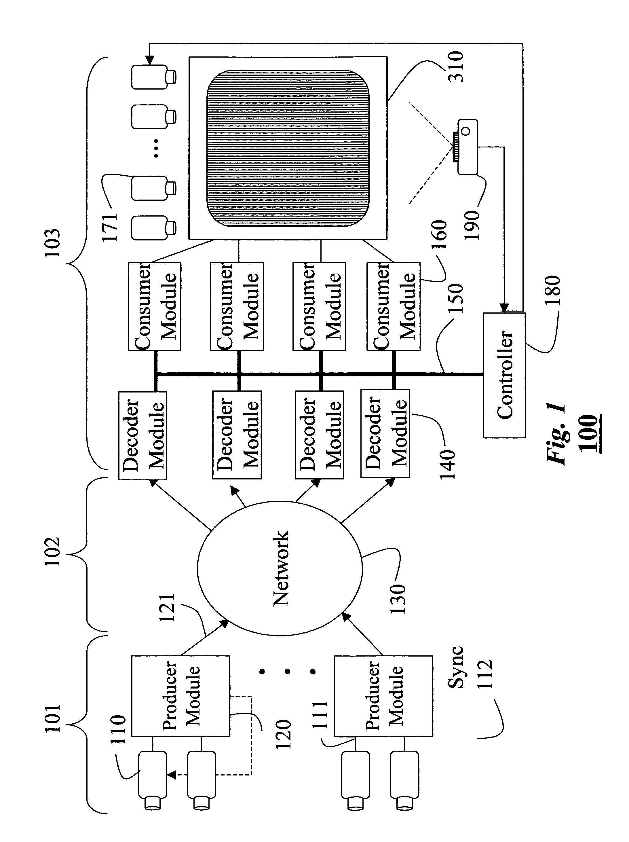
[0066]FIG. 1 shows a 3D TV system according to our invention. The system 100 includes an acquisition stage 101, a transmission stage 102, and a display stage 103.

[0067] The acquisition stage 101 includes of an array of synchronized video cameras 110. Small clusters of cameras are connected to producer modules 120. The producer modules capture real-time, uncompressed videos and encode the videos using standard MPEG coding to produce compressed video streams 121. The producer modules also generate viewing parameters.

[0068] The compressed video streams are sent over a transmission network 130, which could be broadcast, cable, satellite TV, or the Internet.

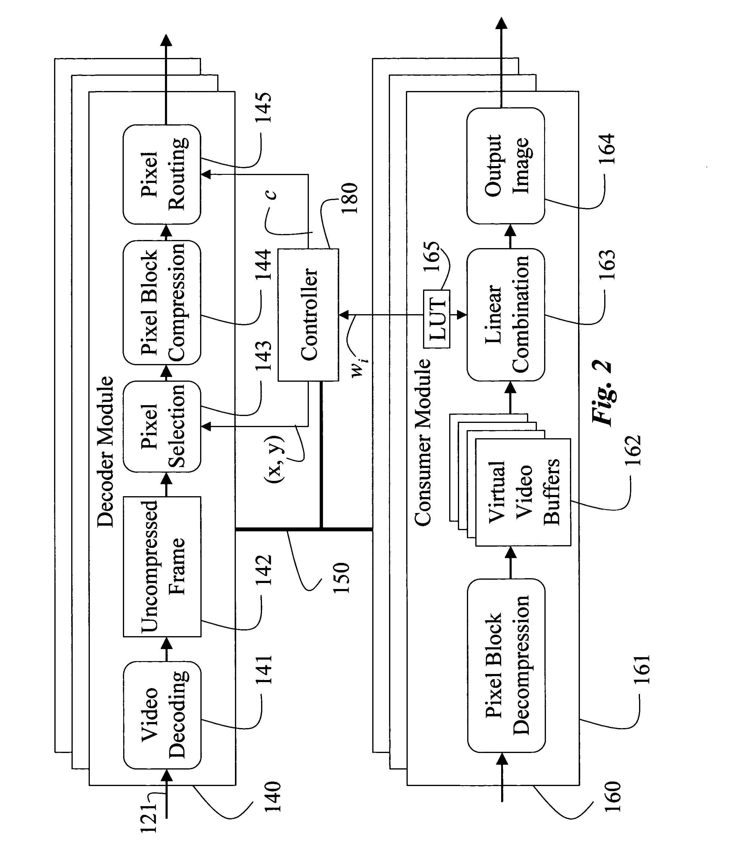
[0069] In the display stage 103, the individual video streams are decompressed by decoder modules 140. The decoder modules are connected by a high-speed network 150, e.g., gigabit Ethernet, to a cluster of consumer modules 160. The consumer modules render the appropriate views and send output images to a ...


PUM


Abstract

A three-dimensional television system includes an acquisition stage, a display stage and a transmission network. The acquisition stage includes multiple video cameras configured to acquire input videos of a dynamically changing scene in real-time. The display stage includes a three-dimensional display unit configured to concurrently display output videos generated from the input videos. The transmission network connects the acquisition stage to the display stage.

Description

FIELD OF THE INVENTION [0001] This invention relates generally to image processing, and more particularly to acquiring, transmitting, and rendering auto-stereoscopic images. BACKGROUND OF THE INVENTION [0002] The human visual system gains three-dimensional information in a scene from a variety of cues. Two of the most important cues are binocular parallax and motion parallax. Binocular parallax refers to seeing a different image of the scene with each eye, whereas motion parallax refers to seeing different images of the scene when the head is moving. The link between parallax and depth perception was shown with the world's first three-dimensional display device in 1838. [0003] Since then, a number of stereoscopic image displays have been developed. Three-dimensional displays hold a tremendous potential for many applications in entertainment, advertising, information presentation, tele-presence, scientific visualization, remote manipulation, and art. [0004] In 1908, Gabriel Lippmann,...

Claims


Application Information

Patent Timeline
Patent Type & Authority Applications(United States)
IPC IPC(8): H04N7/26H04N13/00
CPCH04N13/0059H04N13/0242H04N19/44H04N19/00H04N19/597H04N13/0404H04N13/305H04N13/243H04N13/194
Inventor PFISTER, HANSPETERMATUSIK, WOJCIECH
Owner MITSUBISHI ELECTRIC RES LAB INC
Why Eureka
Try Eureka