Catadioptric objective system and objective system

a catadioptric and objective technology, applied in the field of catadioptric objective systems, can solve the problems of difficult to measure and control the very small distance between the converging point and the storage medium, and the limitation of the reduction of the beam spot by conventional lenses, so as to minimize the fluctuation of the converging point with the thickness change of the adhesive agent, the effect of small thickness and good optical performan

Inactive Publication Date: 2008-04-15
KONICA MINOLTA OPTO
View PDF7 Cites 0 Cited by
  • Summary
  • Abstract
  • Description
  • Claims
  • Application Information

AI Technical Summary

Benefits of technology

[0010]An object of the present invention is to provide a catadioptric objective system and an objective system which are of a simple structure, which can form a micro beam spot with small aberrations and which can position a converging point closer to a storage medium easily.

Problems solved by technology

However, the minimization of a beam spot by use of conventional lenses has reached the limit.
However, since the lens surface has a curvature, it is difficult to measure and control the very small distance between the converging point and the storage medium.
However, a process of forming a fine structure such as a very small opening on the curved lens surface by use of an electronic beam includes a very difficult work such as focusing of the electronic beam.
Accordingly, it is difficult to suppress a spherical aberration and a coma aberration, and off-axis aberrations, particularly, the coma aberration are large.

Method used


Image

  • Catadioptric objective system and objective system
  • Catadioptric objective system and objective system
  • Catadioptric objective system and objective system

Examples


fourth embodiment

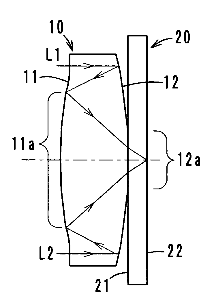
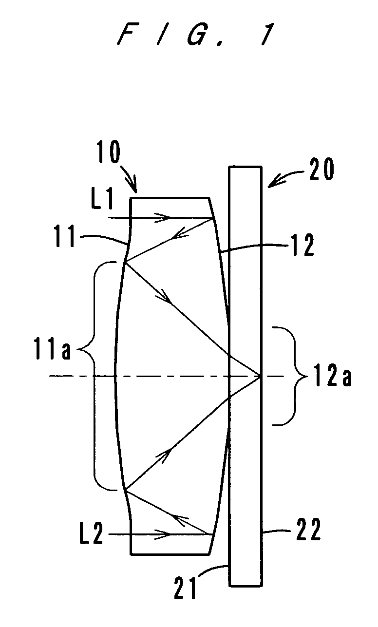
[0034]FIGS. 1, 4, 6 and 8 show the respective structures of catadioptric objective systems according to a first, a second, a third and a FIGS. 2, 5, 7 and 9 show the respective wavefront aberration characteristics of these catadioptric objective systems.

[0035]Each of the catadioptric objective systems according to the first through fourth embodiments comprises a catadioptric objective lens 10 and a light transmitting plate 20. The catadioptric objective lens 10 has a first surface 11 and a second surface 12. The first surface 11 has a positive optical power and transmits incident rays. The second surface 12 has a positive optical power and reflects the incident rays. The second surface 12 has a plane portion 12a in the center.

[0036]The light transmitting plate 20 has a third surface 21 and a fourth surface 22 which are substantially parallel to each other, and the third surface 21 is bonded to the second surface 12 of the catadioptric objective lens 10.

[0037]In FIGS. 1, 4, 6 and 8,...

first embodiment

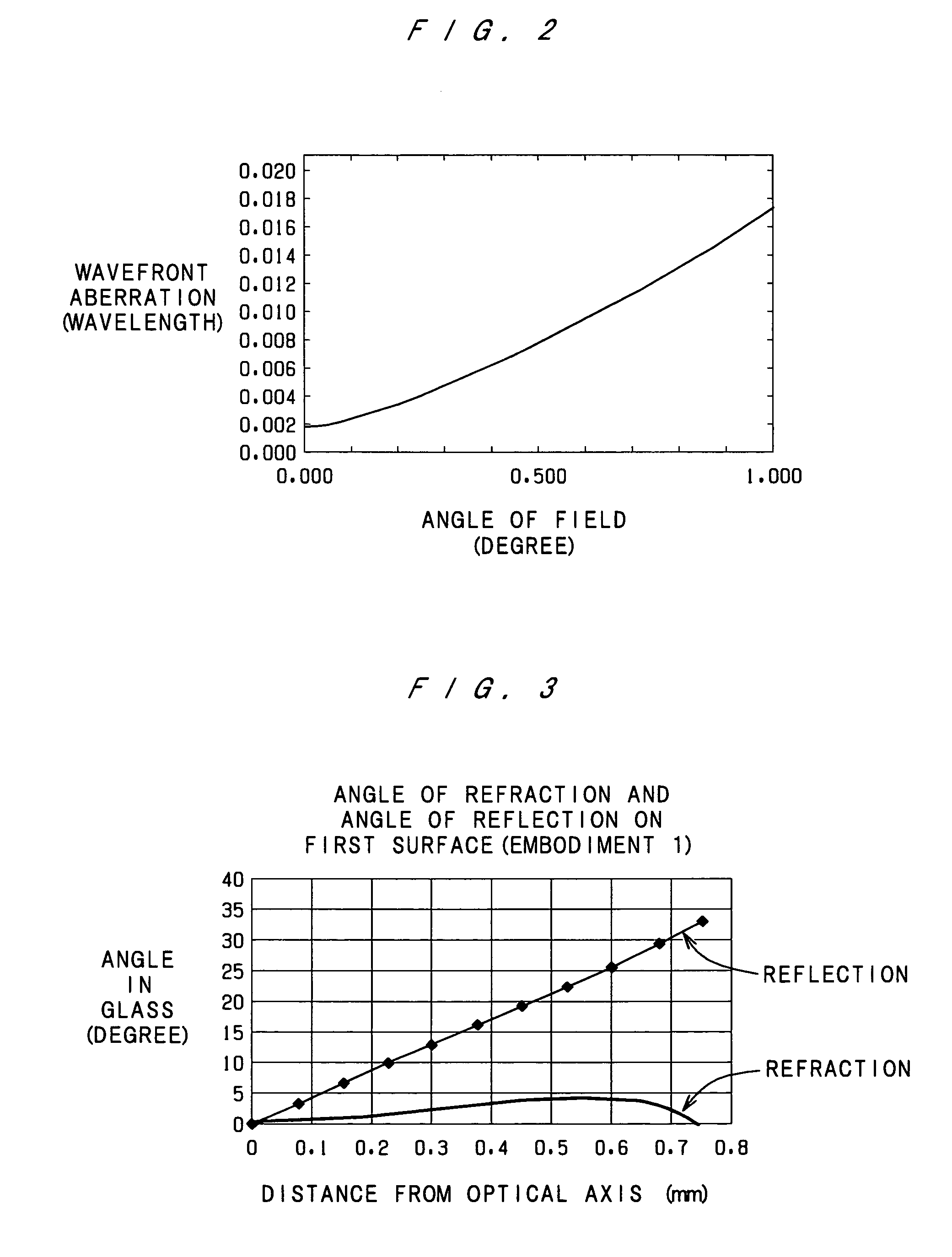
[0086]FIG. 3 is a graph which shows the angle of refraction of incident rays performed by the first surface 11 of the objective lens 10 and the angle of reflection of the rays which enter into the first surface 11 again after being reflected by the second surface 12 (=incident angle) in the The axis of abscissas indicates the distance (mm) from the optical axis of the catadioptric objective lens 10, and the axis of ordinates indicates the angle (degree). The angle of refraction of a ray incident to a point on the first surface 11 of the objective lens 10 is different from the angle of reflection of a ray incident to the same point on the first surface 11, and the characteristic (transmission / reflection) of the coating of the third kind is determined from the difference.

[0087]The dielectric multilayer coating may be, for example, a 40-layer coating shown by Table 7. In Table 7, the material with a refractive index of 2.2 is TiO2, and the material with a refractive index of 1.5 is Si...


PUM

PropertyMeasurementUnit
angleaaaaaaaaaa
refractive indexaaaaaaaaaa

Abstract

A catadioptric objective system used for storage and / or reproduction of information by use of an optical near field. The catadioptric objective system is composed of a catadioptric objective lens and a light transmitting plate. The lens has a first surface and a second surface. The first surface has a positive optical power and transmits incident rays. The second surface has a positive optical power and reflects incident rays, and a plane portion is formed in the center of the second surface. The light transmitting plate has a third surface and a fourth surface which are substantially parallel to each other, and the third surface is bonded to the second surface. Incident rays pass through the first surface and are reflected by the second surface. Thereafter, the rays enter into the first surface again and are reflected by the first surface. Then, the rays pass through the plane portion of the second surface, and the rays are converged in vicinity of the fourth surface.

Description

[0001]This application is based on Japanese application No. 2003-368964 filed on Oct. 29, 2003, the content of which is herein incorporated by reference.BACKGROUND OF THE INVENTION[0002]1. Field of the Invention[0003]The present invention relates to a catadioptric objective system, and particularly to a catadioptric objective system which is used for forming a micro beam spot, and more particularly to a catadioptric objective system which is suited to be used for storage and / or reproduction of information by use of an optical near field.[0004]2. Description of Related Art[0005]In the art of optical storage / reproduction, in order to form a micro beam spot, generally, it is desired to converge a light beam to the diffraction limit by use of an optical system with the highest possible numerical aperture. However, the minimization of a beam spot by use of conventional lenses has reached the limit. This means that objective lenses which propagate light in the air have been improved to ha...

Claims


Application Information

Patent Timeline
Patent Type & Authority Patents(United States)
IPC IPC(8): G11B7/00G02B13/18G02B17/08G11B7/135G11B7/1372G11B7/1387
CPCG11B7/1387G11B2007/13725
Inventor KONNO, KENJI
Owner KONICA MINOLTA OPTO
Why Eureka
Try Eureka