Off-axis variable focus and aberration control mirrors and method

a technology of aberration control and mirror, applied in the direction of mirrors, mountings, instruments, etc., can solve the problems of significantly more complex interface and control schemes, and achieve the effect of reducing optical aberrations and reducing optical aberrations in the image formed by the reflected light beam

Active Publication Date: 2009-02-24
MONTANA STATE UNIVERSITY
View PDF18 Cites 2 Cited by
  • Summary
  • Abstract
  • Description
  • Claims
  • Application Information

AI Technical Summary

Benefits of technology

[0010]In another aspect of the invention, a method of providing an image with reduced optical aberrations using a deformable optical element having a reflective surface is provided. The method can be achieved by displacing the reflective surface along an axis generally orthogonal to the reflective surface so that the reflective surface deforms into an approximation of a sectioned surface of a paraboloid; and providing a light beam along an incident axis oblique to the sectioned surface such that optical aberrations in the image formed by the reflected light beam is reduced.

Problems solved by technology

In some applications a high degree-of-freedom mirror may be suitable to provide the same correction that a low degree-of-freedom mirror offers, but at the expense of a significantly more complex interface and control scheme.

Method used


Image

  • Off-axis variable focus and aberration control mirrors and method
  • Off-axis variable focus and aberration control mirrors and method
  • Off-axis variable focus and aberration control mirrors and method

Examples


examples

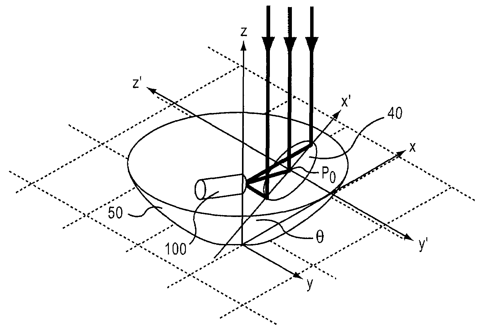
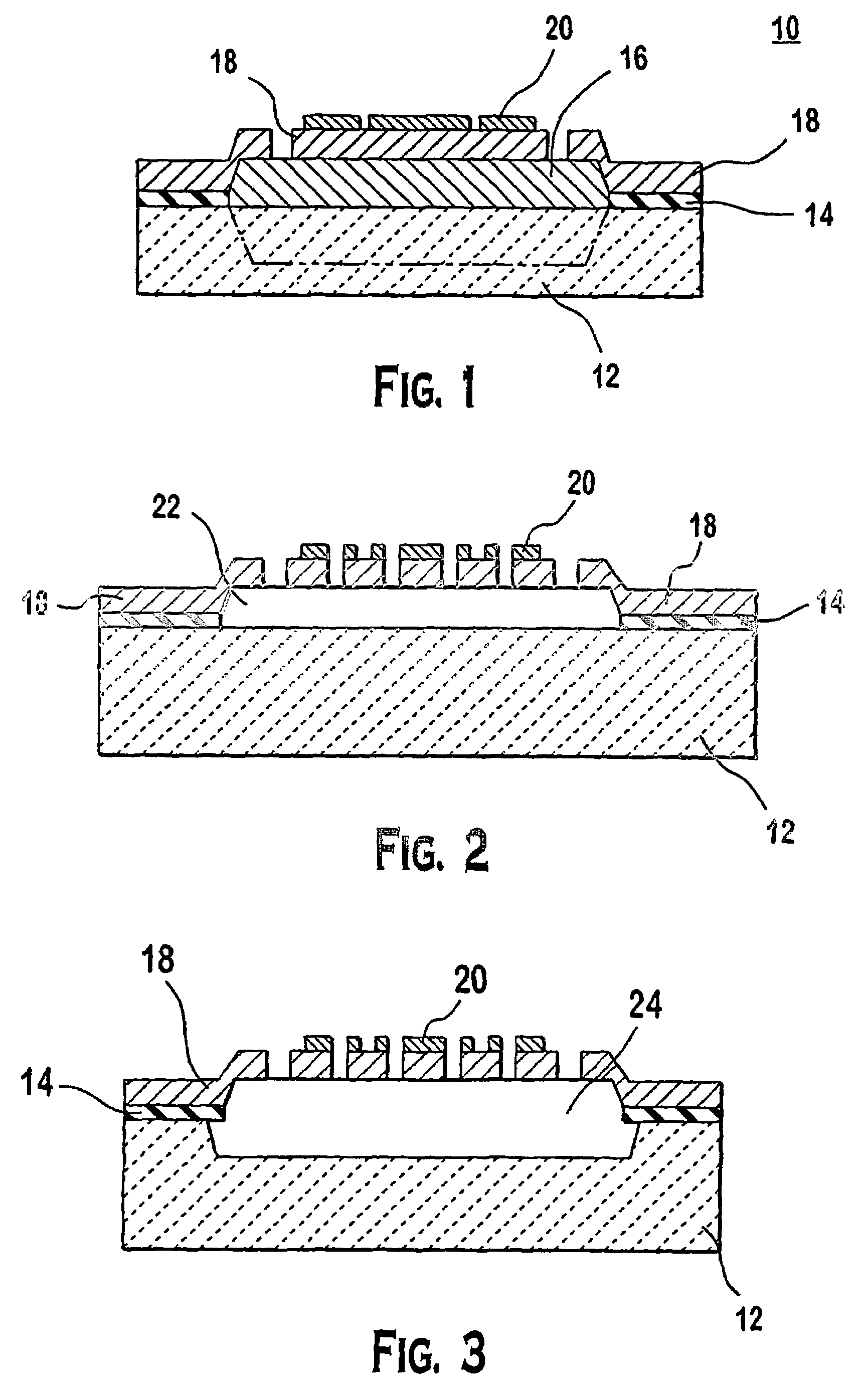
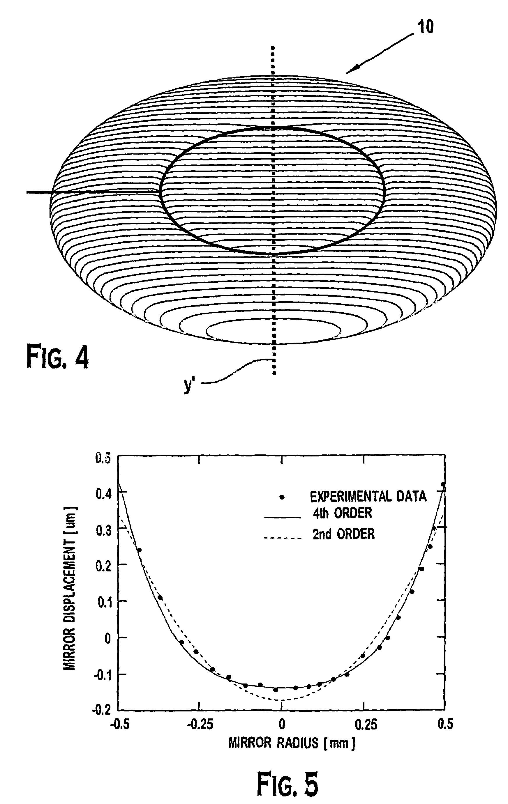
[0034]It is believed that by using an optical element 10 with an elliptical boundary (as shown and described in the preferred embodiments), the optical element 10 reduces the astigmatism introduced by a circular membrane mirror. In the preferred embodiment of the optical element 10, the optical element can be mirrors having dimensions of 1.414 mm by 1 mm, for the length major and minor axes respectively, resulting in an ellipticity of 1.414. Two actuation zones can be used in these examples to provide control over spherical aberration. Perimeter segmentation allows for a lower actuation voltage and improved surface figure of the resulting devices. It has been demonstrated that deflections of up to 2.7 microns for the optical element 10 can be provided, while maintaining optical aberration of the reflected wavefront to less than (λ÷8), measured at λ=660 nm.

[0035]The required optical mirror shape for off-axis focusing depends upon the imaging system configurations. For infinite conjug...


PUM


Abstract

An optical element with multi-layer composites that deforms to reduce optical aberrations in off-axis optic. Methods are also described in relation to the optical element.

Description

CROSS REFERENCE TO RELATED APPLICATION[0001]This application is a U.S. national phase application under 35 U.S.C. § 371(c) of PCT Application No. PCT / US2004 / 001896, filed Jan. 26, 2004 and claims the benefit of priority of U.S. Application No. 60 / 442,315, filed Jan. 24, 2003, which is hereby incorporated by reference in its entirety.STATEMENT REGARDING FEDERAL RIGHTS[0002]This invention was made with government support under grant number DE-FG02-01ER45869, awarded by the Dept. of Energy. The government has certain rights in the invention.FIELD OF THE INVENTION[0003]This invention relates generally to deformable mirrors. In one aspect, the invention also relates to focus control using deformable mirrors. In addition, this invention also relates to methods of using the deformable mirrors. Further, this invention also relates to a method of fabricating the deformable mirrors.BACKGROUND OF THE INVENTION[0004]All publications and patent applications herein are incorporated by reference t...

Claims


Application Information

Patent Timeline
Patent Type & Authority Patents(United States)
IPC IPC(8): G02B5/08G02B26/08
CPCG02B26/06G02B26/0825
Inventor HIMMER, PHILLIP A.DICKENSHEETS, DAVID L.
Owner MONTANA STATE UNIVERSITY
Why Eureka
Try Eureka