

Distributed sterilizer system
a sterilizer and distribution system technology, applied in the direction of disinfection, transportation and packaging, cleaning using liquids, etc., can solve the problems of poor odor, hygiene concerns, and limited delivery methods of ozonated water to certain scales and types of applications with an average efficiency, so as to optimize the efficiency of the sterilizer system
- Summary
- Abstract
- Description
- Claims
- Application Information
AI Technical Summary
Benefits of technology
Problems solved by technology
Method used
Image



Examples
first embodiment
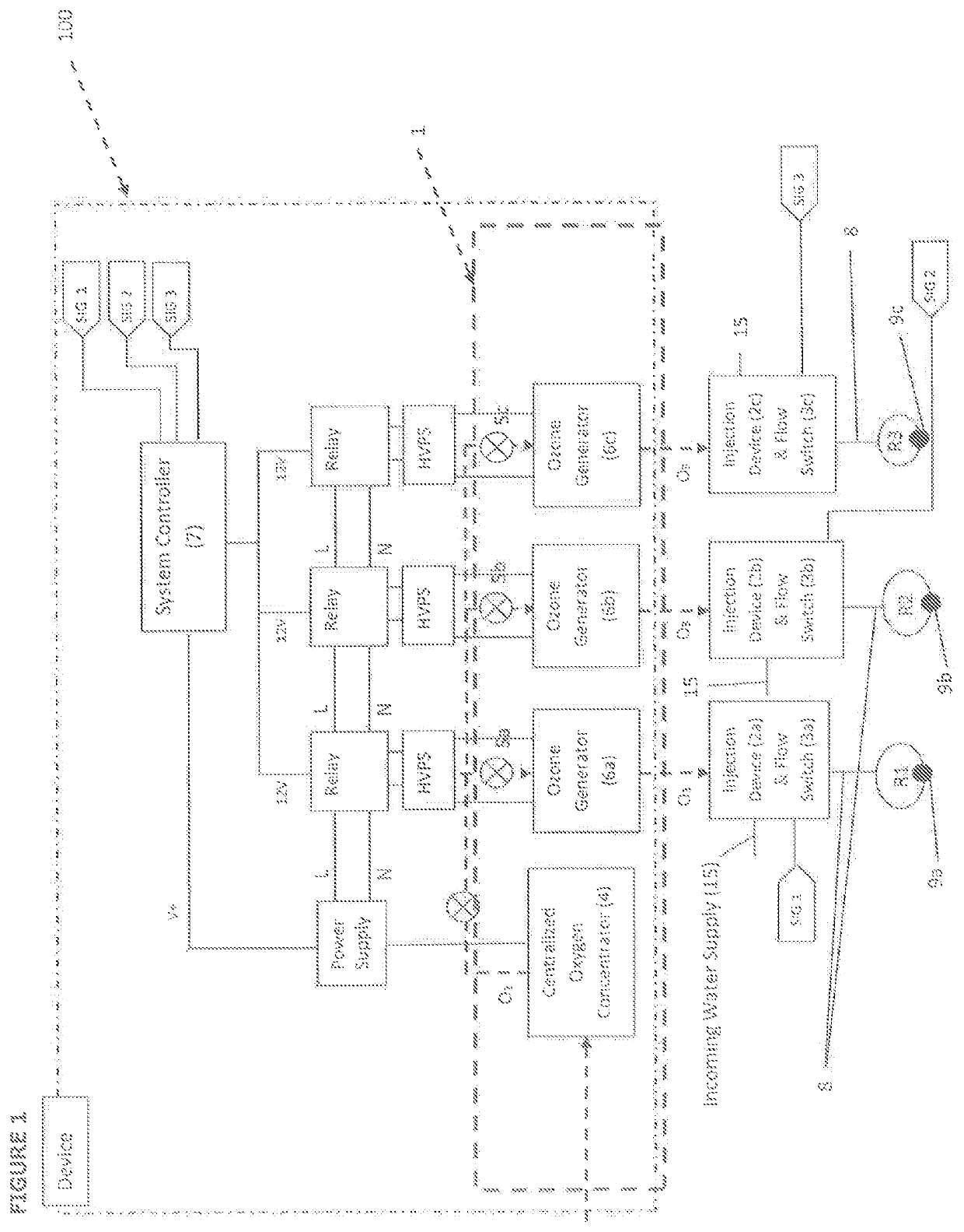
[0039]FIG. 1 is a block diagram which illustrates a distributed sterilizer system 100 for distributing ozone water to a plurality of rooms R1, R2, R3 which has an ozone generation system 1, a plurality of injection devices 2a, 2b, 2c, a plurality of flow switches 3a, 3b, 3c, a plurality of water outlets 9a, 9b, 9c and a delivery piping system 8. The plurality of rooms, R1, R2, R3 are different sections in a kitchen area in which ozone water is used for washing in the washing section, butchery section and food preparation section.
[0040]The ozone generation system 1 comprises a centralized oxygen concentrator 4, three oxygen flow meters 5a, 5b, 5c, and three ozone generators 6a, 6b, 6c. The outdoor air is directed to the ozone generation system 1 in which it is first directed to the centralized oxygen concentrator 4. In the centralized oxygen concentrator 4, the supply of outdoor air containing 21% of oxygen combined with nitrogen and a mixture of other gases. The air supply is then p...
third embodiment
[0049]In this third embodiment, the forming and distribution of ozone water to a plurality of rooms R1, R2, R3, R4 is determined by a similar demand-based configuration as illustrated in FIG. 1. When a user opens any of the water outlet 9a, 9b, 9c, 9d in any of the specific rooms R1, R2, R3, R4 water starts to flow from the incoming water supply 15 to its respective injection devices 2a, 2b, 2c, 2d. Upon detecting the flow of water in the injection devices 2a, 2b, 2c, 2d, the flow switches 3a, 3b, 3c, 3d send signals to the system controller 7 to send signals to the ozone generator 6a, 6b, 6c and the shared ozone generator 6e to generate ozone. The ozone generated from the ozone generators 6a, 6b, 6c and the shared ozone generator 6e is supplied to the injection devices 2a, 2b, 2c, 2d respectively to initiate the mixing of the ozone with the flow of water in the injection devices 2a, 2b, 2c, 2d to form ozone water. The ozone water formed in the injection devices 2a, 2b, 2c, 2d is di...
PUM
| Property | Measurement | Unit |
|---|---|---|
| Flow rate | aaaaa | aaaaa |
Abstract
Description
Claims
Application Information