Safety restraint buckle three-state tongue sensor

a safety restraint buckle and three-state technology, applied in the direction of snap fasteners, pedestrian/occupant safety arrangements, vehicular safety arrangements, etc., can solve the problem of detecting a false positive latch condition by magnetic flux sensor, creating a false positive latch condition, and complicating the manufacturing process

Inactive Publication Date: 2000-07-04
HONEYWELL INC
View PDF9 Cites 16 Cited by
  • Summary
  • Abstract
  • Description
  • Claims
  • Application Information

AI Technical Summary

Problems solved by technology

Because the magnetic flux sensor taught by the '087 patent detects a presence of the tongue by sensing magnetic flux, any stray magnetic field can cause the magnetic flux sensor to detect a false positive latch condition, such as when the tongue is either not within the housing or the tongue is not securely latched within the housing.
The magnetic draw between the magnet and the tongue makes it difficult to handle the magnet during assembly and thus complicates the

Method used


Image

  • Safety restraint buckle three-state tongue sensor
  • Safety restraint buckle three-state tongue sensor
  • Safety restraint buckle three-state tongue sensor

Examples


Embodiment Construction

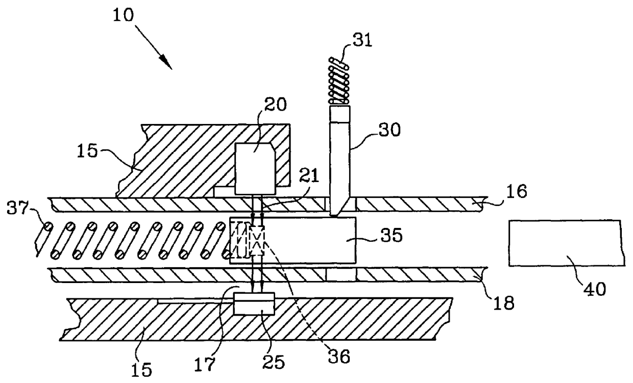
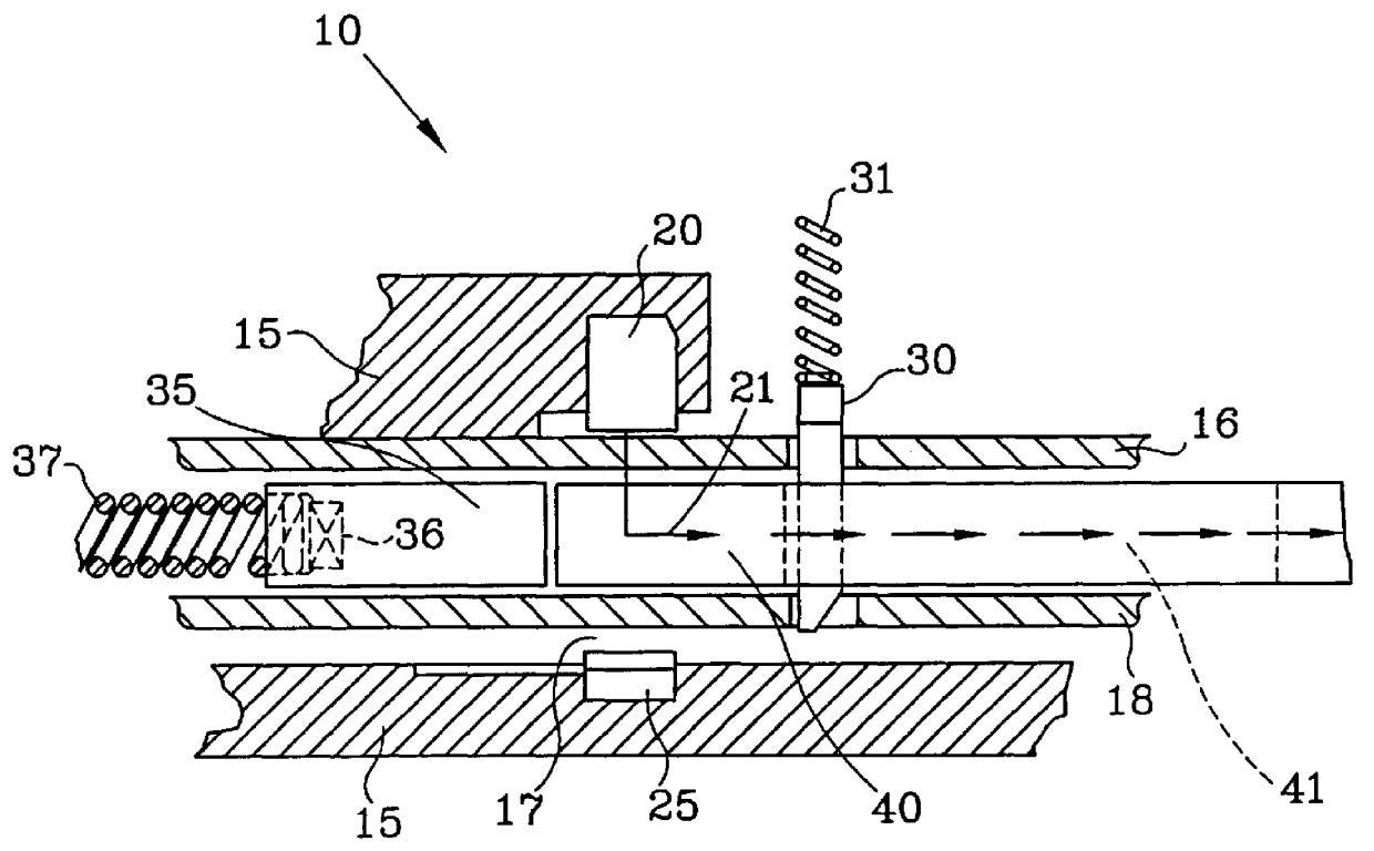
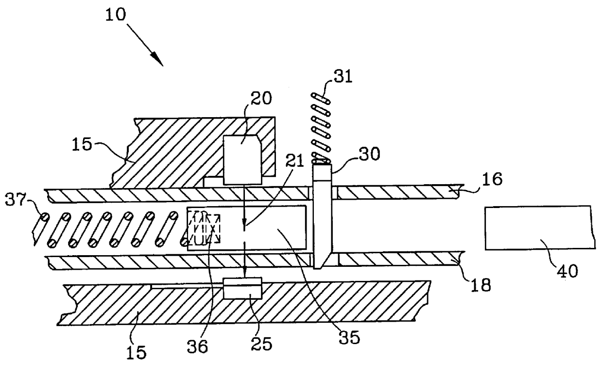
FIGS. 1-3 show three different conditions under which safety restraint buckle 10 of this invention operates. Safety restraint buckle 10 of this invention comprises at least three major moving elements: latch 30 which moves in a vertical direction as shown in FIGS. 1-3; ejector 35 which moves in a horizontal direction as shown in FIGS. 1-3; and tongue 40 which moves in a horizontal direction as shown in FIGS. 1-3.

Safety restraint buckle 10 of this invention can be used to detect at least the three different conditions of safety restraint buckle 10 as shown in FIGS. 1-3. Referring to FIG. 1, latch 30 is in an unlatched position, ejector 35 is in an unloaded position and tongue 40 is disengaged from within housing 15, which corresponds to an unbuckled condition of safety restraint buckle 10. As shown in FIG. 2, latch 30 is in a latched position, ejector 35 is in a loaded position and tongue 40 is in an engaged position, which corresponds to a buckled condition of safety restraint buckl...


PUM


Abstract

A safety restraint buckle apparatus and method wherein a Hall element is mounted with respect to a housing and a magnet is mounted with respect to the housing, at a distance from the Hall element. A latch is movably mounted between a latched position and an unlatched position. A tongue is movable between an engaged position within the housing and a disengaged position. In the engaged position of the tongue, the latch is in the latched position. An ejector with a pole piece or a pole member is movably mounted between a loaded position and an unloaded position. When the ejector is in the unloaded position, the Hall element operates in a high magnetic state. When the ejector is in the loaded position and the tongue is in the engaged position, the Hall element operates in a low magnetic state because the magnetic flux density is shunted through the tongue. When the latch is in the latched position and the tongue is in the disengaged position with the ejector thus held in an intermediate position, the Hall element operates in a mid magnetic state, between the low magnetic state and the high magnetic state, to indicate a false positive latch condition of the safety restraint buckle apparatus.

Description

1. Field of the InventionThis invention relates to a seat buckle and tongue apparatus having a magnetic flux sensor for determining whether a tongue is securely latched within a housing of the seat buckle and tongue apparatus.2. Description of Related ArtKnown seat buckle and tongue assemblies use sensors which are activated when a tongue is inserted into a housing of the seat belt and tongue assembly, in order to detect whether the tongue is securely latched. Conventional seat buckle and tongue assemblies also use magnets and magnetic flux sensors, including Hall sensors, to detect whether the tongue is securely latched.Sasaki, U.S. Pat. No. 4,943,087 discloses a conventional seat buckle and tongue assembly with a magnetic flux sensor to detect whether a tongue is within a housing of the seat buckle and tongue assembly by detecting a magnetic flux from a magnet mounted on the tongue and thus the presence of the tongue.Because the magnetic flux sensor taught by the '087 patent detec...

Claims


Application Information

Patent Timeline
IPC IPC(8): B60R22/00B60R22/48C12N15/12
CPCB60R22/48Y10T24/45623B60R2022/4816
Inventor ENGLER, KEVIN J.
Owner HONEYWELL INC
Why Eureka
Try Eureka