

Door handle module
a technology for door handles and handle devices, applied in anti-theft devices, locks, instruments, etc., can solve the problems of missing modern handle devices, handle devices, and long series production period of handle devices for vehicles, so as to improve the functions of the handle device 202, the effect of ensuring the safety of the user and avoiding mechanical impacts
- Summary
- Abstract
- Description
- Claims
- Application Information
AI Technical Summary
Benefits of technology
Problems solved by technology
Method used
Image

Examples
Embodiment Construction
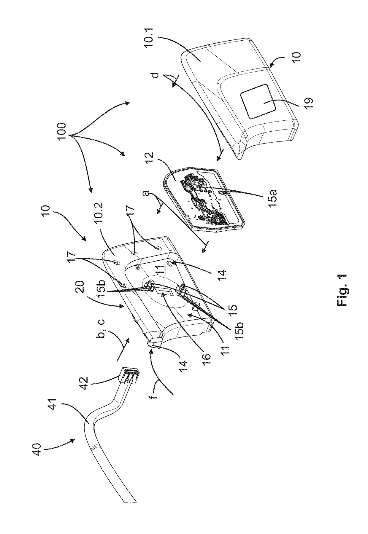
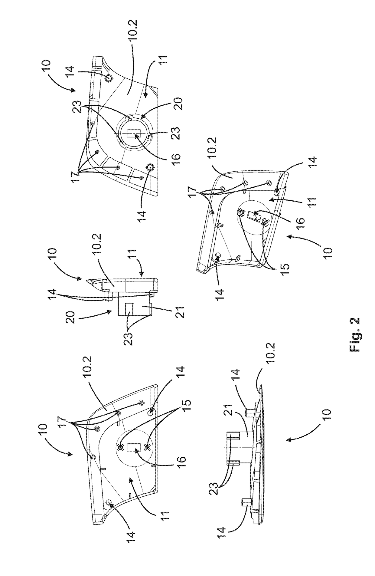
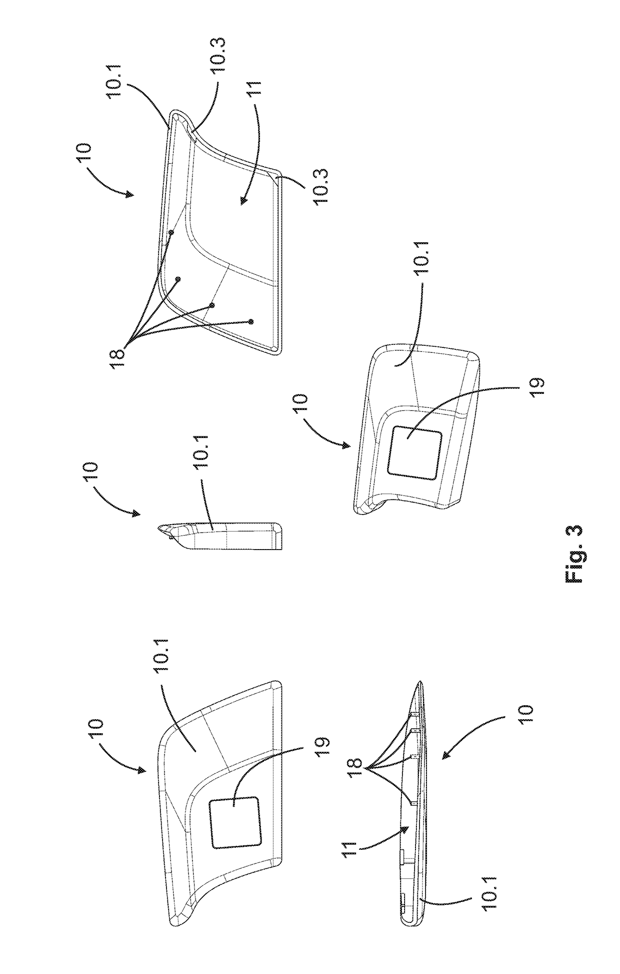
[0068]FIG. 1 shows a door handle module 100 according to the invention prior to the assembly to form a module ready for employ on a handle device 202 of a movable part 201 of a vehicle 200, preferably a commercial vehicle, which is hereinafter schematically shown in FIG. 5. The door handle module 100 is characterized in that it includes a housing 10, in which an electronics unit 12 is completely received. The housing 10 can be formed e.g. of two parts with a first housing part 10.1 (see FIG. 3) and a second housing part 10.2 (see FIG. 2). A receptacle 11 is formed in the housing 10 to receive the electronics unit 12. However, it is likewise possible that the housing 10 is formed in one piece and comprises an opening, through which the electronics unit 12 can be inserted into the receptacle 11. The receptacle 11 can be relatively flat in order to accommodate the electronics unit 12 in the form of a circuit board therein (see FIGS. 1, 2 and 7). To that end, e.g. two receiving pins 15 ...
PUM
 Abstract
Description
Claims
Application Information