
Safety system for engine shutdown, and engines and equipment incorporating the same

a safety system and engine technology, applied in the direction of machines/engines, automatic control of ignition, electric control, etc., can solve the problems of oil dilution, increased production costs, and increased production costs, so as to achieve greater inertia, greater tendency to run, and the effect of widening the cu

Active Publication Date: 2016-09-01
KOHLER CO
View PDF6 Cites 4 Cited by
  • Summary
  • Abstract
  • Description
  • Claims
  • Application Information

AI Technical Summary

Benefits of technology

The present technology is an improved safety system for stopping an engine quickly in the event of an emergency. It prevents the engine from running on and causing harm to equipment manufacturers. The technology achieves this by shutting off the fuel supply to the engine, which stops it from igniting and running. Grounding the ignition coils does not provide any additional braking force on the engine. The technology also includes a stator brake, which is a reliable brake that reduces shutdown time. The control components necessary to stop the engine are located on the engine, so no changes to the wiring of the machine are required to implement the system.

Problems solved by technology

Greater inertia results in a greater tendency to run on, and may make it difficult for equipment manufacturers to achieve the desired width of cut or other performance characteristics while still complying with safety requirements for shutdown time.
In addition, oil dilution may also occur as a result of fuel being drawn into the combustion chambers during shutdown, which then migrates past the piston rings into the crankcase once the engine has stopped.
Thus, no fuel is available that can be ignited, preventing unwanted ignition and running-on of the engine.
Previous efforts to reduce machine shutdown time for lawn mowers with large blades or multiple sets of blades failed to halt blade rotation as quickly as desired.
Grounding the ignition coils effectively stops the engine, but does not prevent auto-ignition of fuel and air.
In addition, grounding the ignition coils can cause undesired oil dilution from unburned fuel migrating into the crankcase.
Further, grounding the ignition coils does not provide any additional braking force on the engine.

Method used


Image

  • Safety system for engine shutdown, and engines and equipment incorporating the same
  • Safety system for engine shutdown, and engines and equipment incorporating the same
  • Safety system for engine shutdown, and engines and equipment incorporating the same

Examples


Embodiment Construction

[0021]The following description of the preferred implementation(s) is merely one example and is in no way intended to limit the technology, its application, or uses.

[0022]The description of illustrative implementations according to principles of the present technology is intended to be read in connection with the accompanying drawings, which are to be considered part of the entire written description. In the description of the preferred implementations of the technology disclosed herein, any reference to direction or orientation is merely intended for convenience of description and is not intended in any way to limit the scope of the present technology. Relative terms such as “lower,”“upper,”“horizontal,”“vertical,”“above,”“below,”“up,”“down,”“left,”“right,”“top,”“bottom,”“front” and “rear” as well as derivatives thereof (e.g., “horizontally,”“downwardly,”“upwardly,” etc.) should be construed to refer to the orientation as then described or as shown in the drawing under discussion. ...


PUM


Abstract

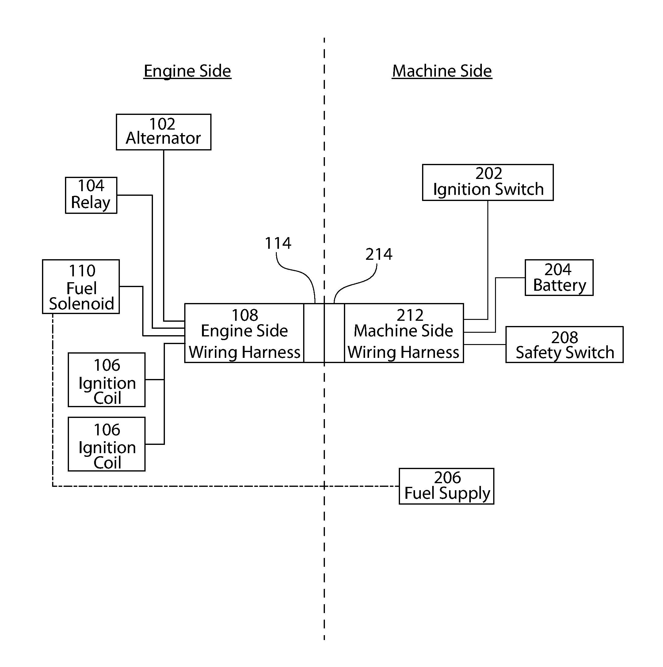
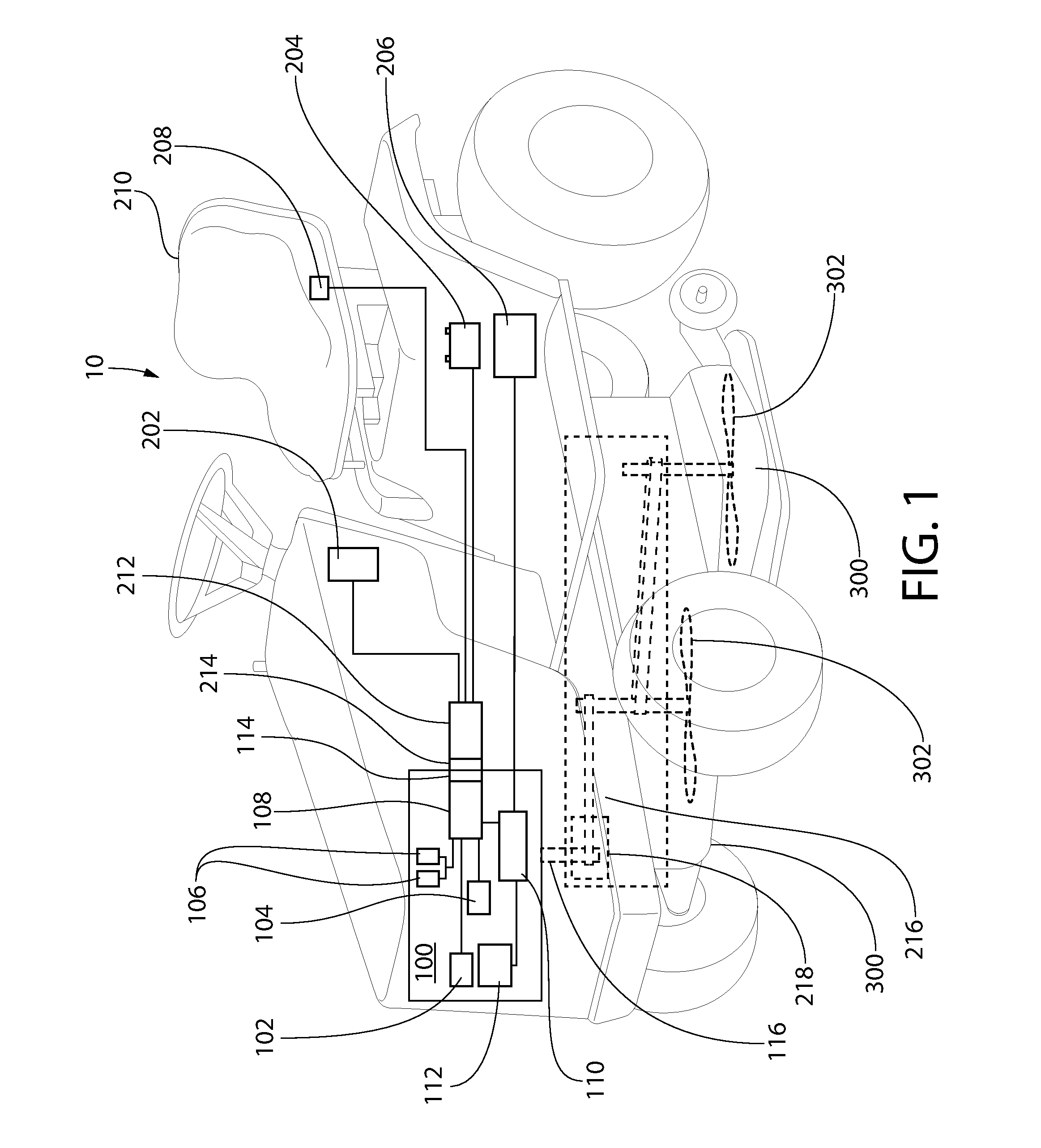
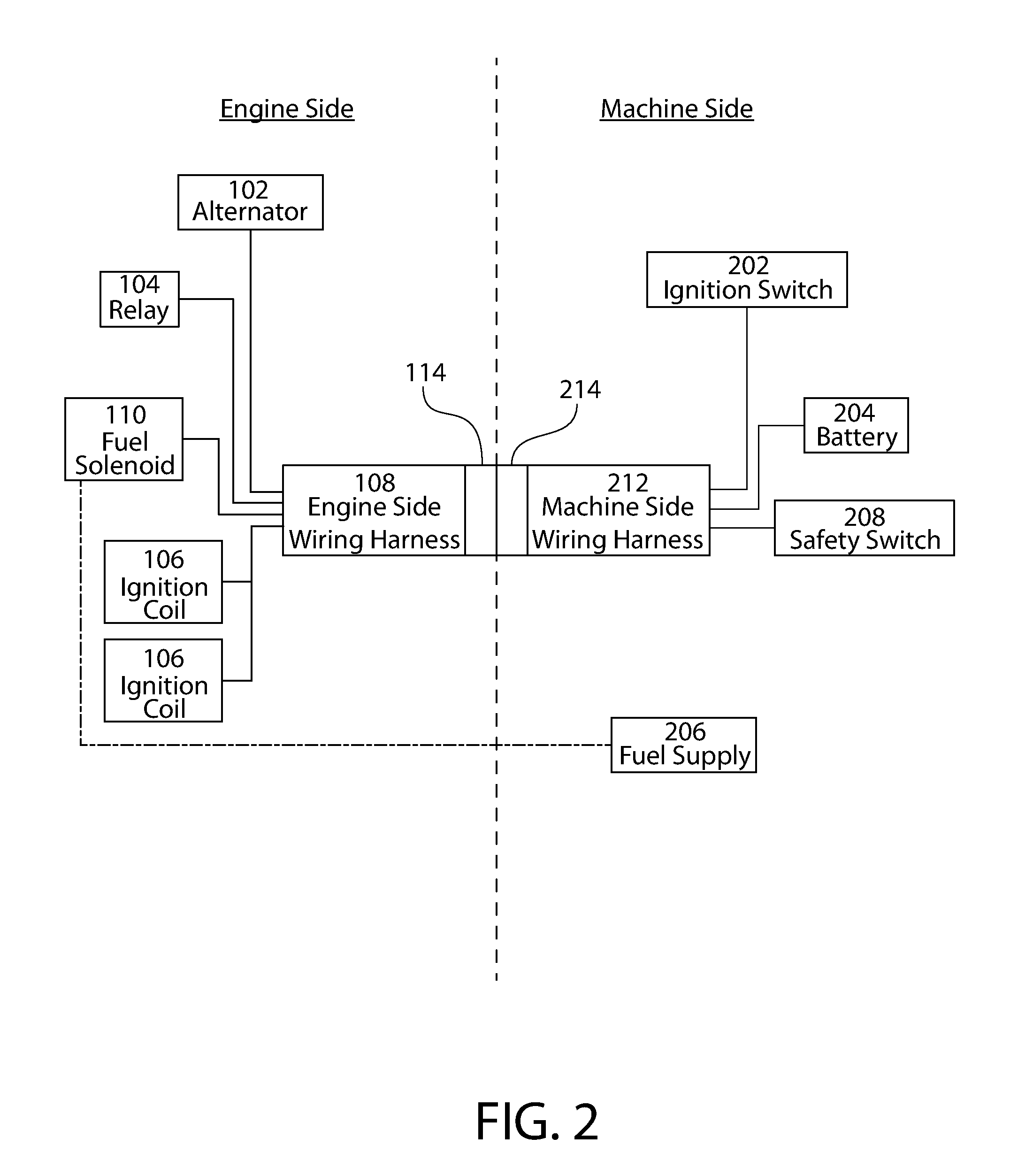
A safety system for engine powered machinery having a fuel cut functionality to promote more rapid shutdown of the rotating parts of the engine powered machinery. In one aspect, the system is implemented as a wiring harness disposed exclusively on the engine which simultaneously disables one or more ignition coils and prevents a fuel-air mixer from supplying a mixture of air and fuel to the engine upon activation of a safety switch. In alternate aspects, the system further comprises a stator brake which is activated by the safety switch to provide additional braking torque on the engine. These features bring the machinery to a rapid halt, further enhancing safety.

Description

CROSS-REFERENCE TO RELATED APPLICATIONS[0001]The present application claims the benefit of U.S. Provisional Patent Application Ser. No. US 62 / 126,351 filed Feb. 27, 2015 and U.S. Provisional Patent Application Serial No. US 62 / 155,707 filed May 1, 2015, the entireties of which are incorporated herein by reference.BACKGROUND OF THE INVENTION[0002]The present technology relates to apparatus, systems, and methods for stopping engine rotation to enhance machine safety. The technology, in certain implementations, is directed to engines and equipment incorporating the same.[0003]Small engine shutdown systems on lawn equipment previously existed in a variety of forms, primarily aimed at stopping engine operation when a safety switch is activated. These systems help to prevent operator and bystander injury and potential machine or property damage. Existing systems focused on disconnecting power from the engine's ignition coil to cease firing of the engine cylinders and halt engine rotation....

Claims


Application Information

Patent Timeline
Patent Type & Authority Applications(United States)
IPC IPC(8): F02D17/04F02D11/10F02D41/22F02B77/08
CPCF02D17/04F02D41/221F02D11/107F02B77/08F02D33/006F02D37/02F02D41/042F02D41/20F02D2041/202F02P3/04F02P9/00A01D34/76A01D34/828F02D41/021F02D2400/06F02P5/045F02P11/00F02M19/00H02K7/18
Inventor GRUELL, JEFFERY D.HARRELD, TIMOTHY D.DOWDY, STEVEN H.
Owner KOHLER CO
Learn More