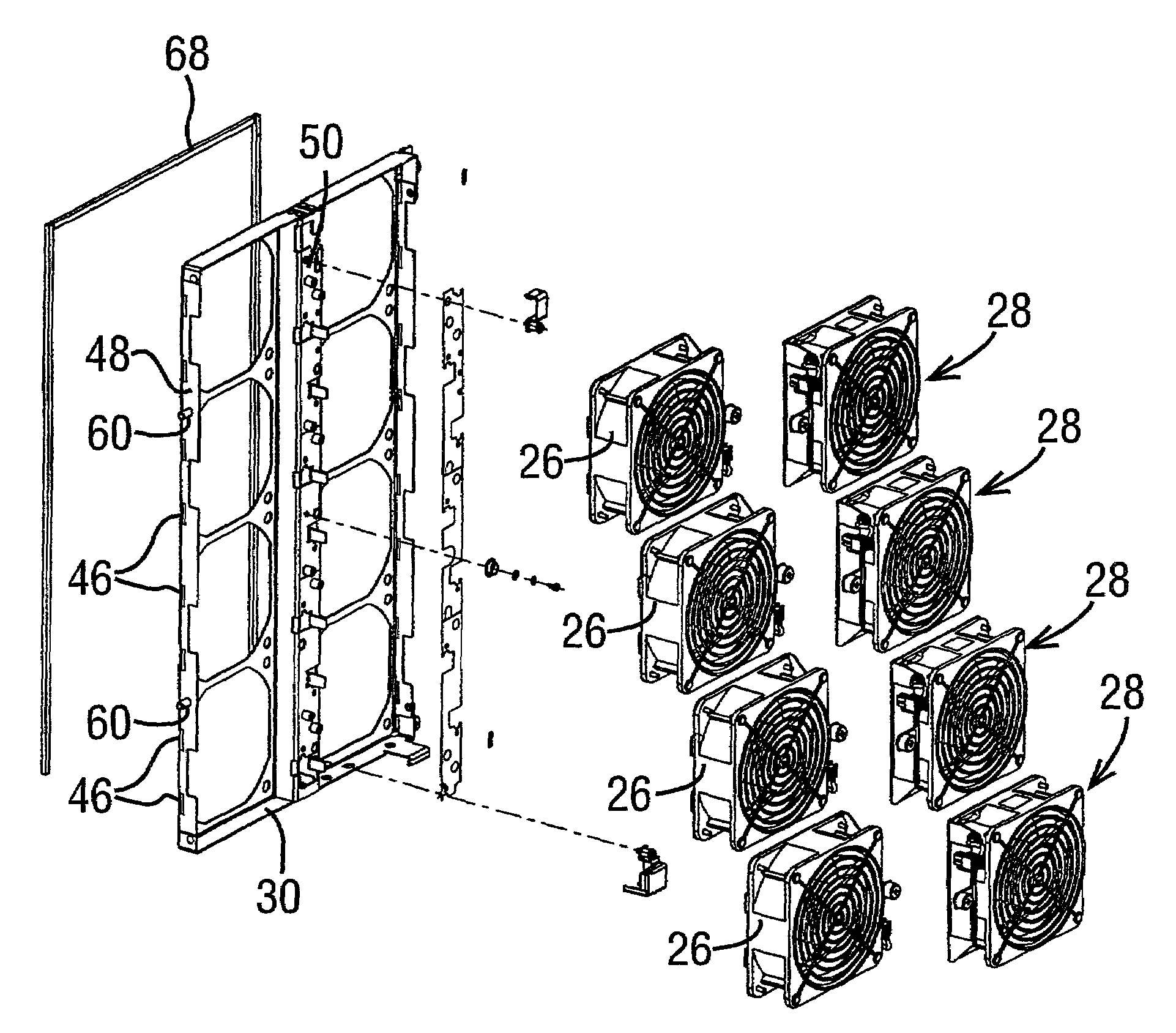
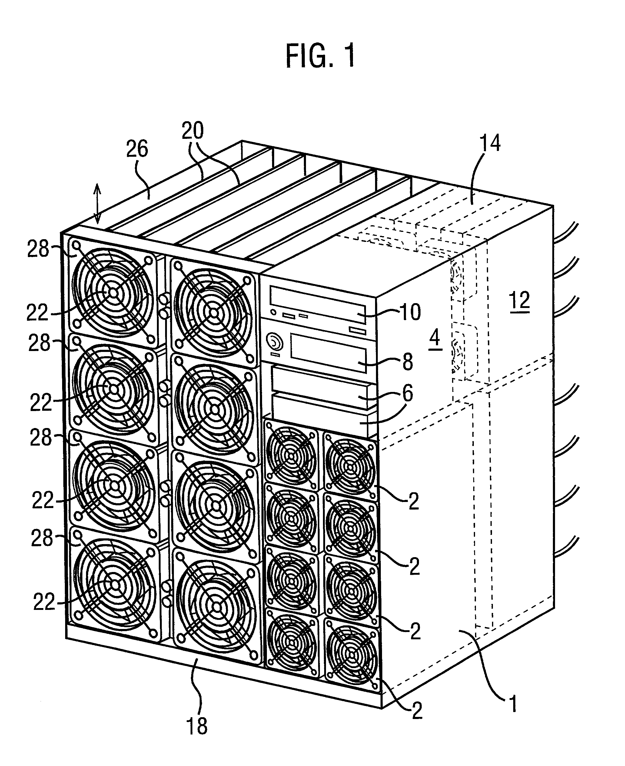
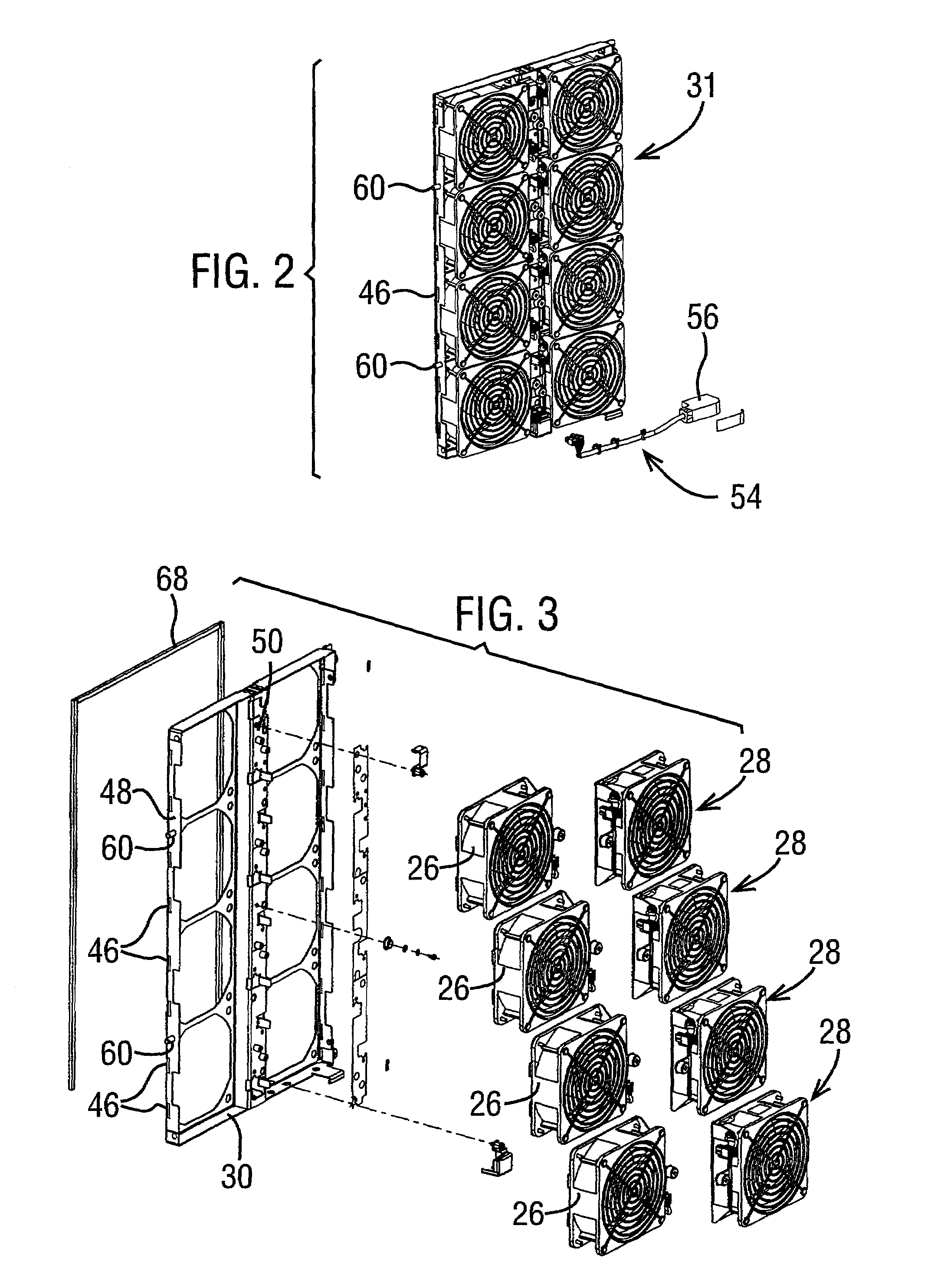
[0007]According to another aspect, there is provided a panel for attachment to the chassis of an
electronics assembly, which comprises a plurality of cooling fans and a holder for the fans, wherein the panel is attachable to, and removable from, the chassis as a
single item, and the panel allows removal of individual fans therefrom and replacement of any fans while attached to the chassis.
[0008]Thus, the chassis and panel according to the invention have the
advantage that, if any fans of the
system fail, the entire array of fans can be removed and replaced relatively quickly by removing the panel from the chassis as a
single item, thereby reducing the
downtime of the
system. Alternatively, if only a single fan has failed or a small number thereof have failed, fans may be removed from the panel individually and replaced, without removing the panel from the chassis. Each fan of the array may, for example, have its own connection to a source of power, and thus enable individual fans to be removed from the panel and replaced while the remaining fans remain in operation, thereby enabling individual fans to be replaced without incurring any downtime.
[0009]The number of fans that are arranged in the panel will depend on the nature and size of the electronics assembly and of the fans, but the number will may be such that will enable a
rectangular array to be formed in the panel having dimensions that correspond to the internal volumes of the assembly. Thus, the panel may, for example, house two, four, six, eight, nine or twelve fans to provide an appropriate
rectangular array. The fans may, at least in the broadest aspect of the invention, differ from one another, but in many cases the fans and the recesses in the panel will be identical, so that the inventory required to service the system will be reduced. Furthermore, it is not necessary for all the fans to be arranged in a single panel. It may, in some designs of equipment be desirable for more than one panel to be present, each panel containing a fraction of the total number of fans.
[0011]The fans will normally be present in the form of a module in which a fan is housed in a generally rectangular body or housing having a central aperture in which the fan motor and blades are located and which allows passage of air therethrough. When employed in such a form, it can usually be a relatively easy and quick operation to change any of the fans in the panel. However, it may be appropriate for the fans to be secured to the holder by an arrangement that requires a tool, e.g. a key or screwdriver, to release it from the holder in order to prevent inadvertent removal. In order to facilitate quick removal and replacement of the fans, the fans may be accommodated in the holder in such a way that they are secured therein by means of a
single element, e.g. a threaded element that requires use of the tool to release. Typically, the fan is attached to the holder by means of at least one cooperating tab and recess or other feature for the same purpose, so that the tab and recess may simply be engaged and the threaded element tightened in order to secure the
fan in the panel. This may conveniently be achieved by including a sheet member on the fan module (the sheet member having an aperture corresponding to the aperture in the fan module body) which provides the tab and also, on the other side of the fan, a support for a captive threaded element. The provision of a sheet member. e.g. formed from
aluminium zinc plated steel that is employed for the chassis, to provide the tabs and the support for the threaded element has the
advantage that any increase in thickness of the panel is minimised. Alternatively it is possible to provide the holder in the form of a frame that extends around the fan but does not extend over any part of the face thereof and so does not add to its thickness.
[0013]The panel may include a
gasket that extends around the periphery of the panel between the panel and the chassis in order to prevent or reduce bypass leakage of air around the fans. The
gasket may be attached to the holder of the panel or to the chassis as desired. In addition or alternatively, the panel may include a
gasket that extends around the periphery of each fan between the fan and the holder in order to prevent or reduce bypass leakage of air around that fan. The gaskets, whether extending around the panel or the individual fans, may be formed from any appropriate material, for example a
textile felt, from plastics or rubber, or from
metal.
[0014]The chassis may contain a monitoring arrangement for monitoring each fan. The monitoring arrangement may, for example, send a message to a central location in order to inform the location of the status of the fans, and in particular, whether or not any fan has developed a fault and needs to be replaced. The monitoring arrangement may be located in the body of the chassis, but it is convenient for it to be located on the panel itself. Such a monitoring arrangement may take the form of a pcb having an LED or other device to inform the
service engineer which fan has developed a fault in addition to sending a message to the central location. Typically, the pcb will be elongated and will extend along the centre of the panel so that a part of the pcb will be adjacent to each of the fans. The arrangement may be located on either side of the panel, but if it is located on the inner side of the panel, i.e. the side of the panel that faces the interior of the chassis when it is attached to the chassis, the arrangement will be protected from accidental damage, for example caused physically or due to
electrostatic discharge.


