Seed singulator housing and agricultural machine equipped with it

a technology of seed singulator and housing, which is applied in the field of seed singulator housing and agricultural machines, can solve the problems of high power requirement of fan system, high power requirement of hydraulic system, and cumbersome and time-consuming to fill so many small bins, so as to reduce the power loss, prevent or reduce the air leakage through the holes that are covered by the same, and reduce the power loss

Active Publication Date: 2012-07-26
VADERSTAD HLDG
View PDF0 Cites 3 Cited by
  • Summary
  • Abstract
  • Description
  • Claims
  • Application Information

AI Technical Summary

Benefits of technology

[0013]By the cover means, air leakage through the holes that are covered by the same is prevented or reduced. It is optimal that the cover means, in the circumferential direction, extends across the entire part of the revolution of a hole in which no seed covers the hole. A considerable decrease of the power loss is achieved even if the cover means does not extend completely over the entire part, e.g., if constructive considerations of space limit that option. Also an extension in the range of 75-100% gives a significant decrease of the power loss.
[0014]An additional positive effect by this solution is that the air current and hence the turbulence in the sow housing decrease. This means a decreased risk of the seed trapped in a hole being disturbed by the air agitation in the sow housing. A disturbance may result in a seed clearing from a hole in an incorrect position on the seed disc or seed drum, or that a seed is brought by the air current and the turbulence beside and past the inlet to the seed hose, in both cases this causes a “skip”.

Problems solved by technology

A limitation of the machine type described above is that each drill row has one singulating disc and consequently each row has one bin for seeds.
For a user, it is cumbersome and time-consuming to fill so many small bins.
A problem of positive pressure systems, irrespective of whether it is about sow housings having plane seed discs or seed drums, is the high power requirement of the fan system, which often is hydraulically driven.
Together with other hydraulics of these sowing machines, the power requirement of the hydraulic system is often so high that the capacity of a common standard tractor is not always sufficient.
A great part of the power loss that arises in a sow housing having positive pressure over a seed element such as a seed disc or a seed drum is the air leakage that arises in the holes of the seed element that do not contain seed.

Method used


Image

  • Seed singulator housing and agricultural machine equipped with it
  • Seed singulator housing and agricultural machine equipped with it
  • Seed singulator housing and agricultural machine equipped with it

Examples


embodiment examples

DESCRIPTION OF EMBODIMENT EXAMPLES

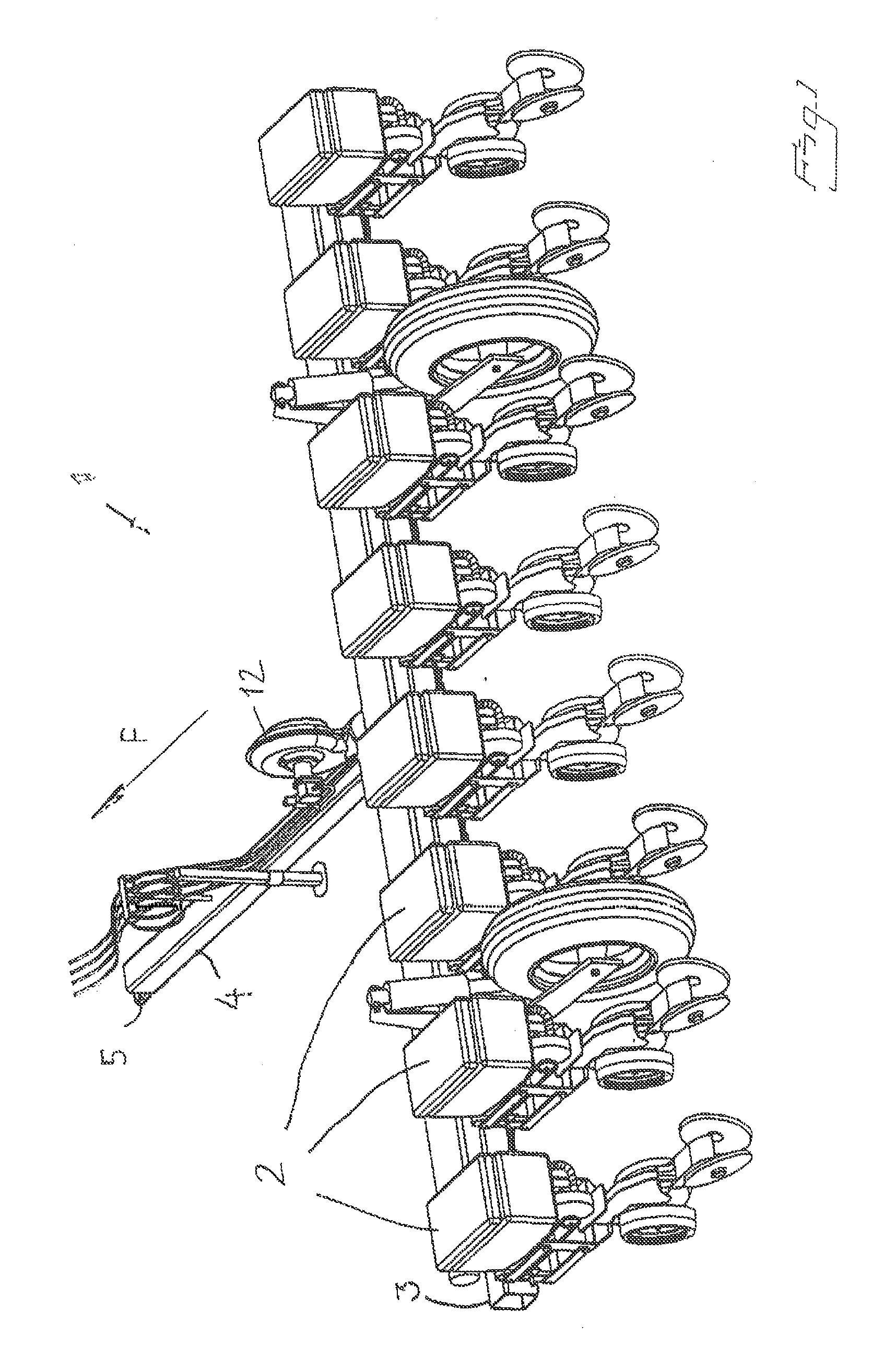
[0052]FIG. 1 shows a perspective view of an agricultural machine in the form of a planter 1 according to an embodiment example of the invention. The planter embraces a number of, in this example eight, drilling units 2, each one of which attached to a transverse steel joist 3. By means of a coupling means 5, arranged at a free end of a longitudinal beam 4, the planter is arranged to be coupled behind a traction vehicle and propagated in a direction indicated by the arrow F in FIG. 1. During the motion of the machine 1 across the soil that is to be sown, each one of the drilling units 2 is arranged to form a drill furrow in the direction of travel of the machine, in order to place one seed at a time along the drill furrow to form a row of seeds in the direction of travel F of the machine, as well as to close the furrow. Via overhead wires, a fan 12 is arranged to supply compressed air to each drilling unit 2, for purposes that will be described below...


PUM


Abstract

A sow housing for piecemeal sowing of seeds. The sow housing includes a seed bin and a rotating seed element having a wall that has a plurality of through holes. Each hole is arranged to, during a first part of the revolution of the hole, retain a seed as a consequence of pressure difference between the two sides of the wall. A cover means is arranged to cover each hole during a second part of the revolution of the hole.

Description

FIELD OF THE INVENTION[0001]The present invention relates to a sow housing for piecemeal sowing of seeds, which sow housing comprises a seed holder and a rotating seed element having a wall that has a plurality of through holes, each hole being arranged to, during a first part of the revolution of the hole, retain a seed as a consequence of pressure difference between the two sides of the wall, which pressure difference is accomplished by a positive pressure being maintained on the side of the wall where the seeds are situated, and each hole being arranged to, during a second part of the revolution of the hole, pass a release area for the removal of seed from the hole.BACKGROUND OF THE INVENTION[0002]Sow housings of the kind in question are used in planters where the seeds are sowed singulated one by one.[0003]In that connection, there are requirements of capacity, simplicity to handle the machines and the sow precision that the machines deliver. In order to provide good conditions ...

Claims


Application Information

Patent Timeline
Patent Type & Authority Applications(United States)
IPC IPC(8): A01C7/12
CPCA01C7/044A01C7/046A01C7/081A01C7/042
Inventor GILSTRING, GERT
Owner VADERSTAD HLDG
Why Eureka
Try Eureka