Power control system and method of excavator

A technology for power control and excavators, which is applied to earth movers/excavators, construction, etc., can solve problems such as power and response speed decline, slow movement of working devices, and unstable machine operation, so as to reduce the speed and improve the performance of the machine. Functional power and torque improvement effect

Inactive Publication Date: 2010-09-01
SANY HEAVY MACHINERY
View PDF4 Cites 75 Cited by
  • Summary
  • Abstract
  • Description
  • Claims
  • Application Information

AI Technical Summary

Problems solved by technology

However, if the speed drops too much, the output power will decrease instead. When the speed drops to about 7% lower than the no-load speed, the output power will reach the limit. Below the limit speed, the output power will drop suddenly, and the displacement of the pump will drop. Causes the working device to move slowly, the power and response speed decrease, and the machine operation is unstable

Method used


Image

  • Power control system and method of excavator
  • Power control system and method of excavator
  • Power control system and method of excavator

Examples


Embodiment 1

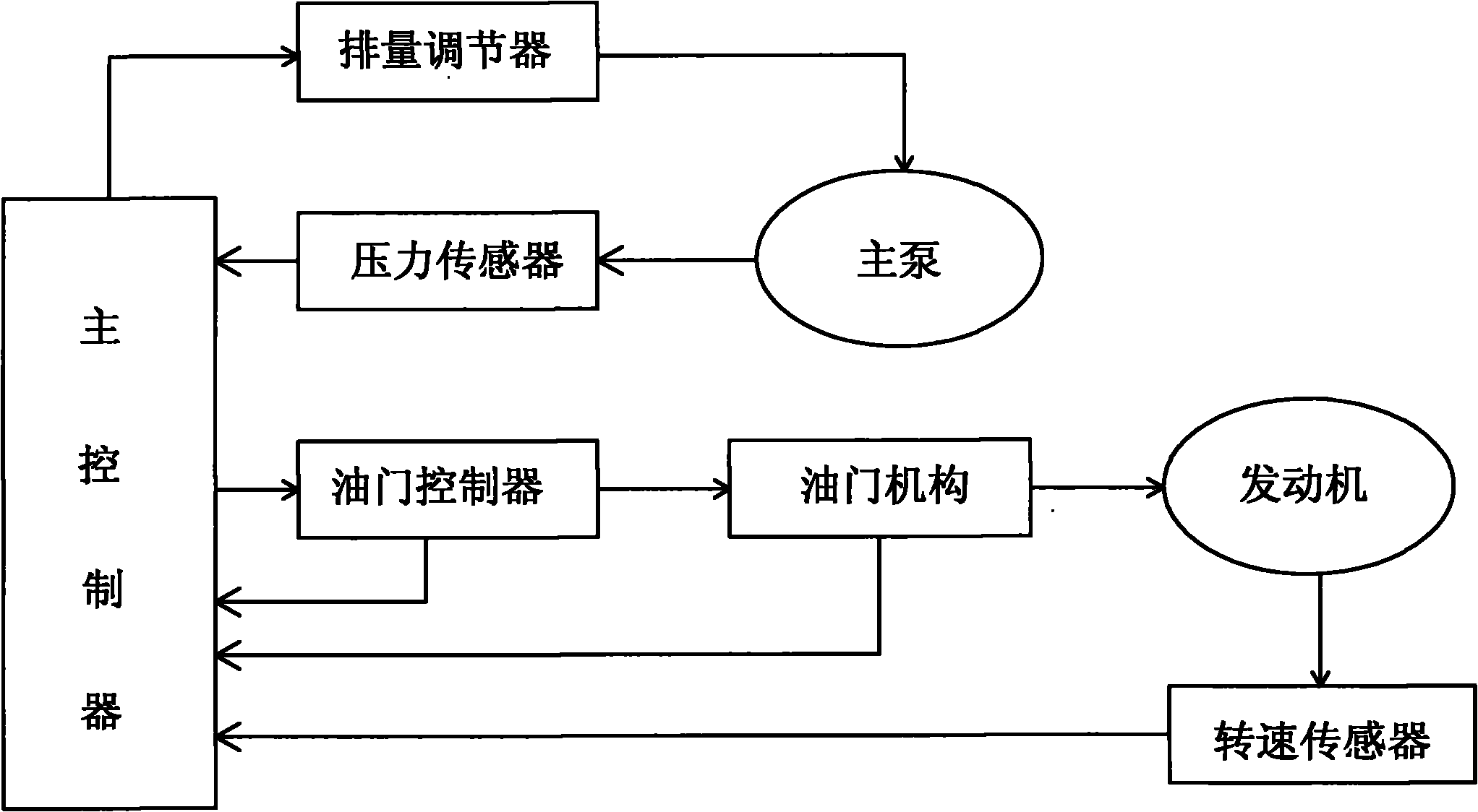
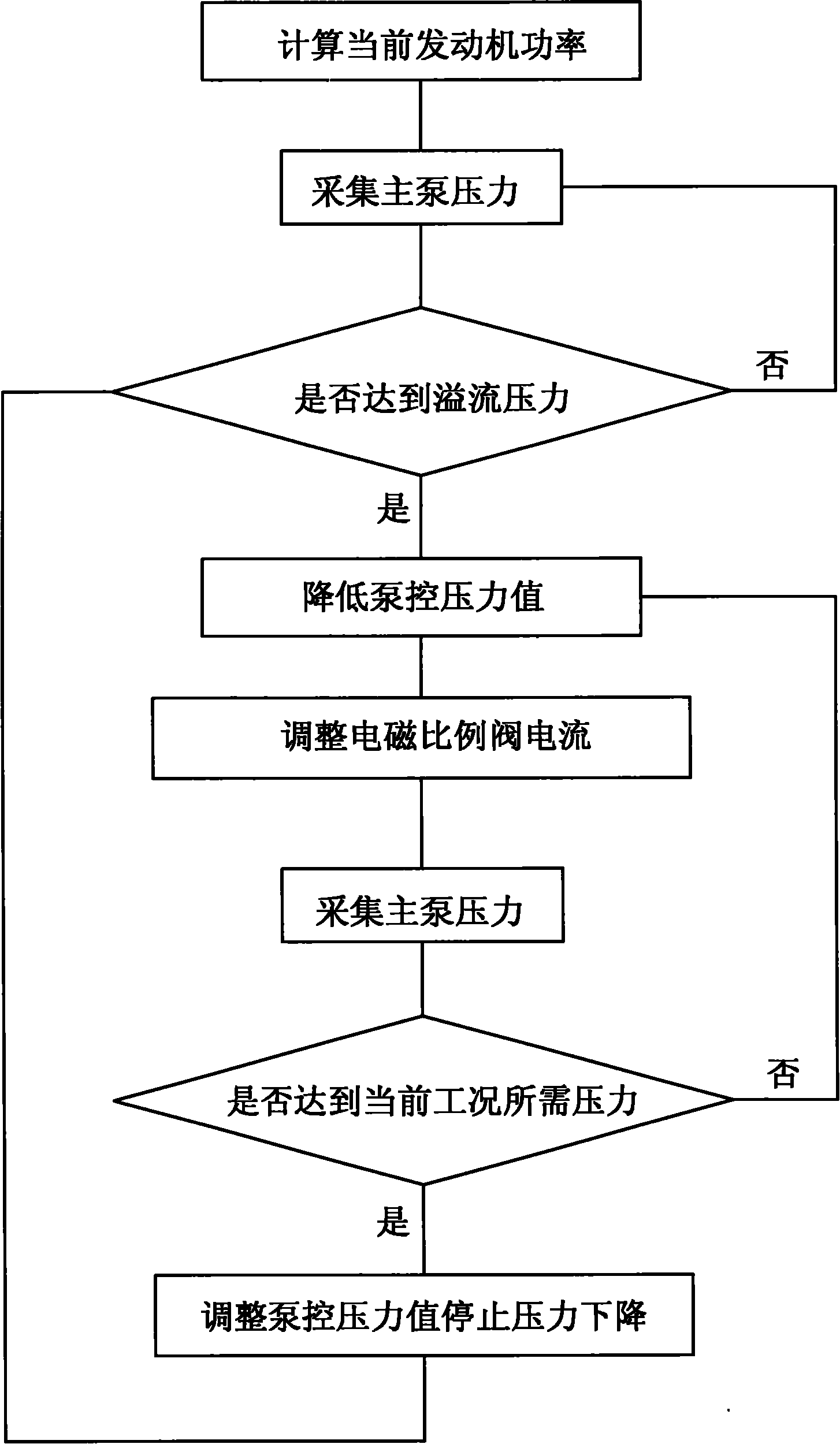
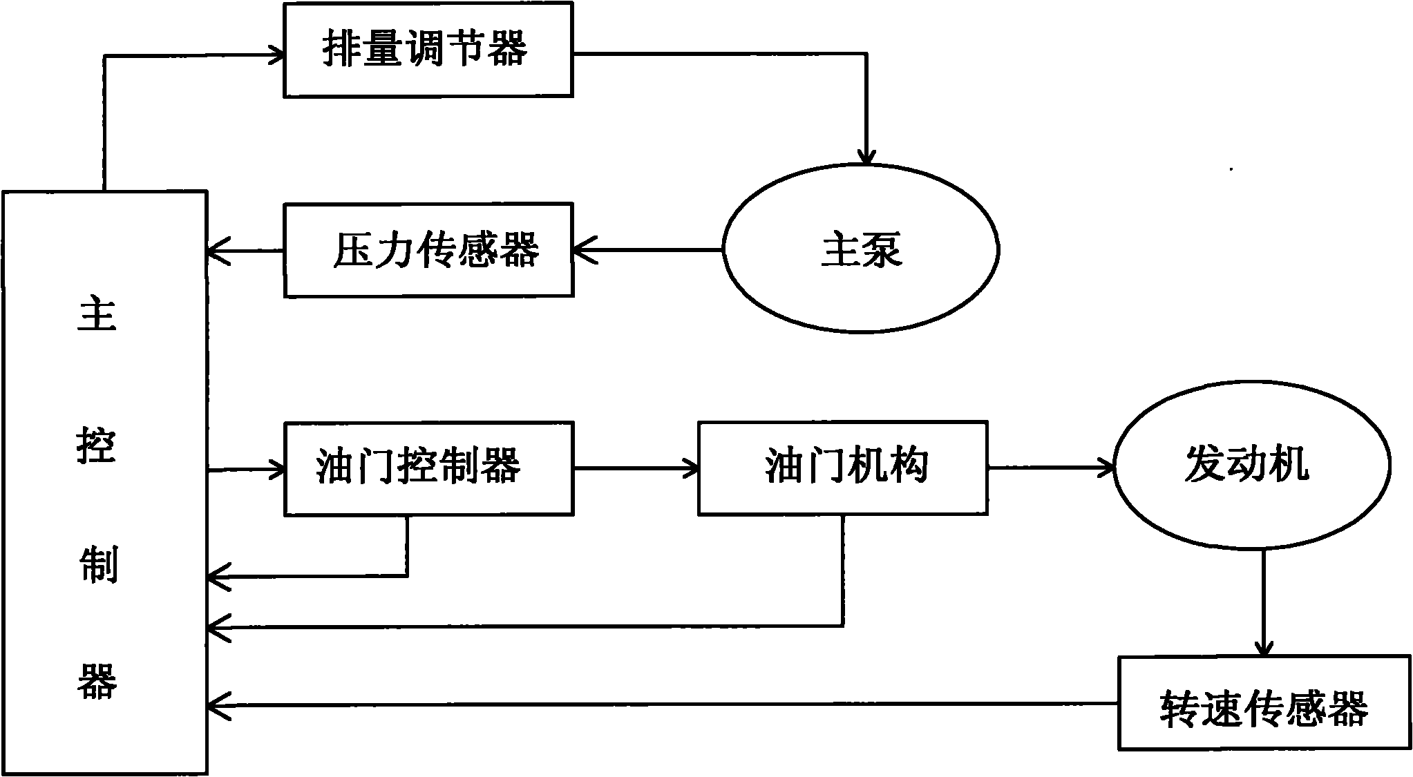
[0020] Example 1: see figure 1 , 2 As shown, an excavator power control system includes a pressure sensor and an electromagnetic proportional valve arranged at the outlet of the main pump, a rotational speed sensor arranged at the engine, and a load calculation module arranged in the main controller of the excavator. The sensor, the information output end of the rotational speed sensor and the control end of the electromagnetic proportional valve are respectively connected to the main controller, and are calculated by the load calculation module and output: (1) The engine speed target value or change amount is applied to the engine; (2) The target value or change amount of the throttle position of the engine is applied to the engine; (3) The target value or change amount of the displacement of the main pump is applied to the displacement regulator of the main pump; the control method is as follows: (1) The excavator At low load, it is controlled by positive flow control mode;...


PUM


Abstract

The invention discloses a power control system of an excavator. The power control system is characterized by comprising a pressure sensor, a main pump displacement regulator, a revolution speed sensor and a loading calculation module, wherein the pressure sensor and the main pump displacement regulator are arranged on the outlet of a main pump, the revolution speed sensor is arranged on an engine, and the loading calculation module is arranged in the main controller; the pressure sensor, the revolution speed sensor and the main pump displacement regulator are respectively connected with the main controller and output engine revolution speed, throttle position and main pump displacement after being calculated by the loading calculation module to respectively control an actuating mechanism. The method is as follows: low load is a positive flow control mode; high load: a. when engine revolution speed is more than or equal to no-load speed* (1-7%), controlling by a constant power mode; and b. when the engine revolution speed is less than no-load speed* (1-7%), controlling by a limiting power mode. The invention controls by constant power comprehensive limiting power, gives consideration to the power output of a dynamic system on the premise of ensuring excavating force, dynamically adjusts the matching between the practical power of a hydraulic system and requirements, lowers power loss and reduces oil loss.

Description

technical field [0001] The invention relates to an excavator control system and method, in particular to a system and method for excavator power control. Background technique [0002] The traditional excavator hydraulic system and engine control adopts such a measure: to ensure the power input of the hydraulic system, and to make the input power of the pump reach or even exceed the actual demand power for a long time, so as to ensure that the hydraulic system always works in one. This state of power oversupply can indeed meet the requirements of the work, but it brings a lot of power loss. [0003] In order to use the power of the engine more effectively, a constant power variable pump is usually used. The so-called constant power variable pump is generally said that the product of the pressure of the pump and the flow of the pump is a constant. If this value is greater than the power of the engine, it will be There is what we often call stalling. Therefore, every designer...

Claims


Application Information

Patent Timeline
Patent Type & Authority Applications(China)
IPC IPC(8): E02F9/22
Inventor 代晴华赵志刚涂晓丹逯明
Owner SANY HEAVY MACHINERY
Why Eureka
Try Eureka