A heating circuit for a railway vehicle power supply contact rail

A technology for rail vehicles and heating circuits, applied in the field of rail vehicles, can solve the problems of small resistance value of power supply contact rails, low driving efficiency, vehicles unable to take electricity from the contact rails, etc., and achieve the effects of good safety and high driving efficiency.

Inactive Publication Date: 2019-01-15
ZHUZHOU ELECTRIC LOCOMOTIVE CO
View PDF4 Cites 1 Cited by
  • Summary
  • Abstract
  • Description
  • Claims
  • Application Information

AI Technical Summary

Problems solved by technology

[0008] 1) Because the impedance value of the power supply contact rail itself is relatively small, a large short-circuit current is required to produce an obvious heating effect. In this way, the ground DC power supply will work at a high current for a long time, resulting in the heating of the feed cable and its joints being higher than that of the contact rail. serious
[0009] 2) Once the switches K1 and K2 are closed, the ground DC power supply and the positive and negative contact rails form a DC heating loop ①, then during the period of heating and deicing of th

Method used


Image

  • A heating circuit for a railway vehicle power supply contact rail
  • A heating circuit for a railway vehicle power supply contact rail
  • A heating circuit for a railway vehicle power supply contact rail

Examples


Example Embodiment

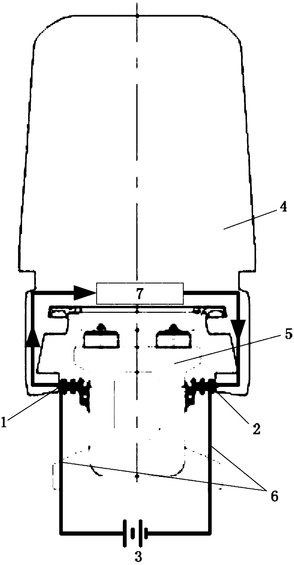
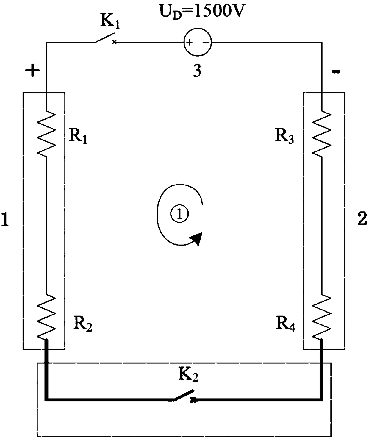
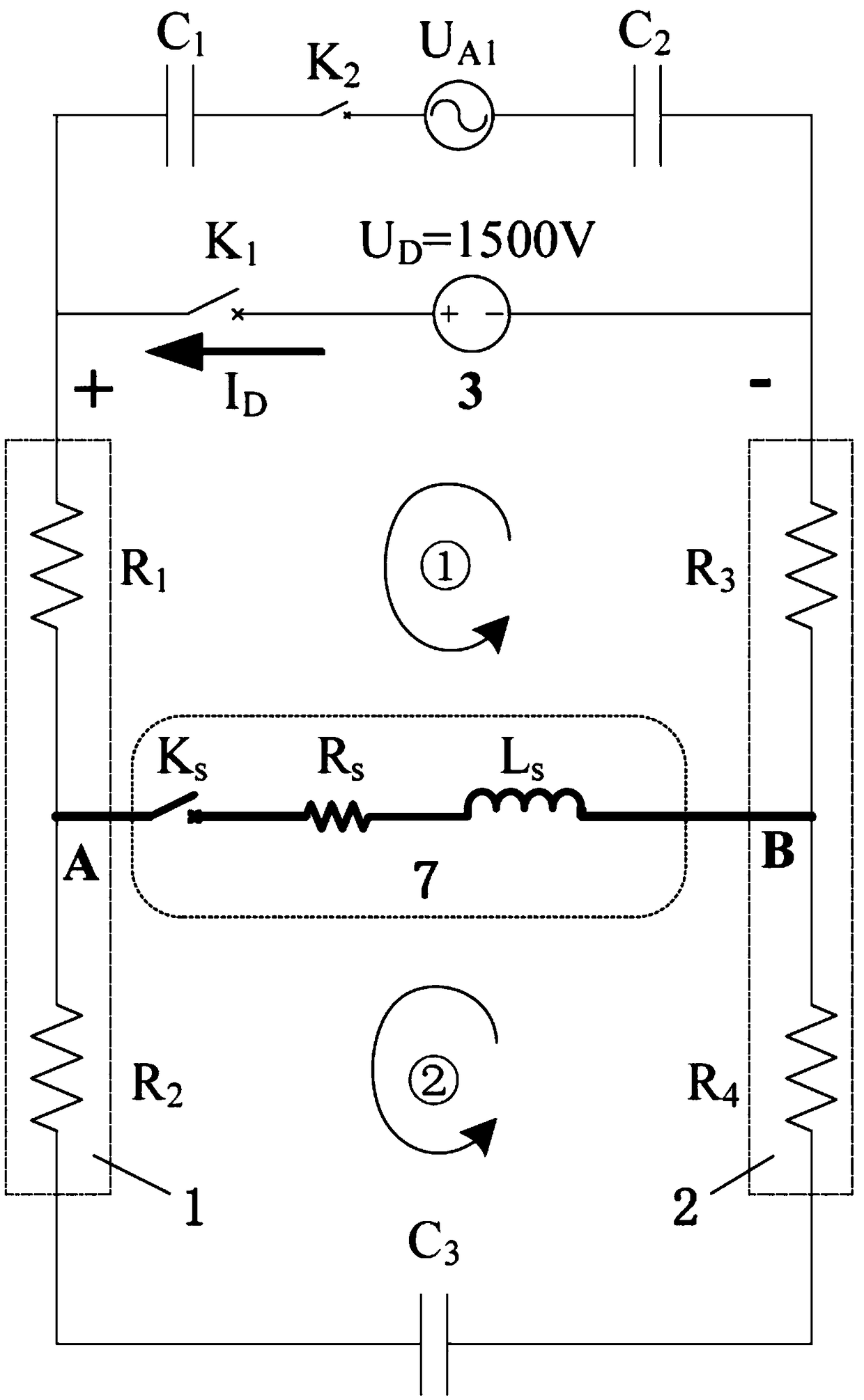
[0021] Such as image 3 As shown, in the rail vehicle power supply contact rail heating circuit, the positive electrode of the ground DC power supply 3 is electrically connected to one end of the positive contact rail 1, the negative electrode of the ground DC power supply 3 is electrically connected to one end of the negative contact rail 2, and the middle section of the positive contact rail 1 is connected to the vehicle load 7 Negative contact rail 2 middle section electrical connection; including AC power U A1 And 3 capacitors, AC power U A1 , The capacitor, the positive contact rail 1, and the negative contact rail 2 form an AC loop.

[0022] The capacitor is divided into the first capacitor C 1 , The second capacitor C 2 , And the third capacitor C 3 , Where the first capacitor C 1 Connected to AC power U A1 Between one end of the positive contact rail 1 and the second capacitor C 2 Connected to AC power U A1 Between one end of the negative contact rail 2 and the third capac...


PUM


Abstract

A heating circuit for a railway vehicle power supply contact rail is disclosed. A positive pole of a ground DC power supply is electrically connected with one end of a positive pole contact rail, thenegative pole of the ground DC power supply is electrically connected with one end of a negative pole contact rail, and the middle section of the positive pole contact rail is electrically connected with the middle section of the negative pole contact rail through vehicle load. The structure is characterized in that the heating circuit includes an AC power supply UA1 and at least one capacitor; the AC power supply UA1, a capacitor, a positive electrode contact rail and a negative electrode contact rail form an AC loop. The heating circuit ensures the continuous and effective heating effect ofthe contact rail on the premise of not affecting the vehicle to obtain power from the contact rail and ensuring the normal operation of the vehicle, does not have any adverse influence on the vehiclepower supply loop, and has good safety and high driving efficiency.

Description

technical field [0001] The invention belongs to the technical field of rail vehicles, in particular to a rail vehicle power supply contact rail heating circuit. Background technique [0002] At present, many rail vehicles at home and abroad, such as medium and low-speed maglev vehicles, subway vehicles, light rail, straddle monorail, etc., adopt DC power supply mode for their external power supply: positive contact rail power supply, negative contact rail return (also use catenary feed, track return), the power supply voltage level is DC 1500V or DC 750V. [0003] figure 1 It is a schematic diagram of the structure of the catenary rail power supply. The patent of the present invention is not limited to describe this method, and is also applicable to the power supply method of catenary feed and rail return. figure 1 Just an example. The key components are as follows: positive contact rail 1, negative contact rail 2, ground DC power supply 3, vehicle 4, track beam 5, feeder...

Claims


Application Information

Patent Timeline
IPC IPC(8): B60M1/30E01H8/08
CPCB60M1/30E01H8/08
Inventor 邓江明佟来生李晓春彭奇彪罗华军
Owner ZHUZHOU ELECTRIC LOCOMOTIVE CO
Why Eureka
Try Eureka