System and method for envelope tracking power supply

a power supply and envelope technology, applied in the field of system and method of envelope tracking power supply, can solve the problems of power loss, unnecessarily heating the power amplifier's components, inefficient operation, etc., and achieve the effect of reducing the power loss of the power amplifier and improving the power efficiency of the wireless system

Active Publication Date: 2013-01-24
TEXAS INSTR INC
View PDF13 Cites 78 Cited by
  • Summary
  • Abstract
  • Description
  • Claims
  • Application Information

AI Technical Summary

Benefits of technology

[0004]A system and method are provided for improving wireless system power efficiency with a variable output power supply, which tracks the envelope of the power amplifier's output to decrease the power amplifier power loss.
[0008]A switch bank includes multiple switches. The switch bank receives on and of signals from a driver, whose input signals are often from a digital predistortion controller. At any moment, only one switch is selected, to provide selected voltage to the output filter. By using the switch bank, an envelope tracking (ET) power supply can enable a rapid change of its output voltage to track the power amplifier peak voltage output.

Problems solved by technology

The power loss, caused by inefficient operation of the power amplifier, unnecessarily heats the power amplifier's components.

Method used


Image

  • System and method for envelope tracking power supply
  • System and method for envelope tracking power supply
  • System and method for envelope tracking power supply

Examples


Embodiment Construction

[0018]In accordance with an aspect of the present invention, a system and method provides an efficient power source that tracks the envelope of a power amplifier's output voltage to decrease the system's power loss, mainly the power amplifier's power loss. In an example embodiment, a power supply is operable to output a step voltage that corresponds to the amplitude of a signal to be transmitted by a power amplifier therefore minimizing the power amplifier's power loss.

[0019]An aspect in accordance with the present invention will now be described with reference to FIGS. 1-5.

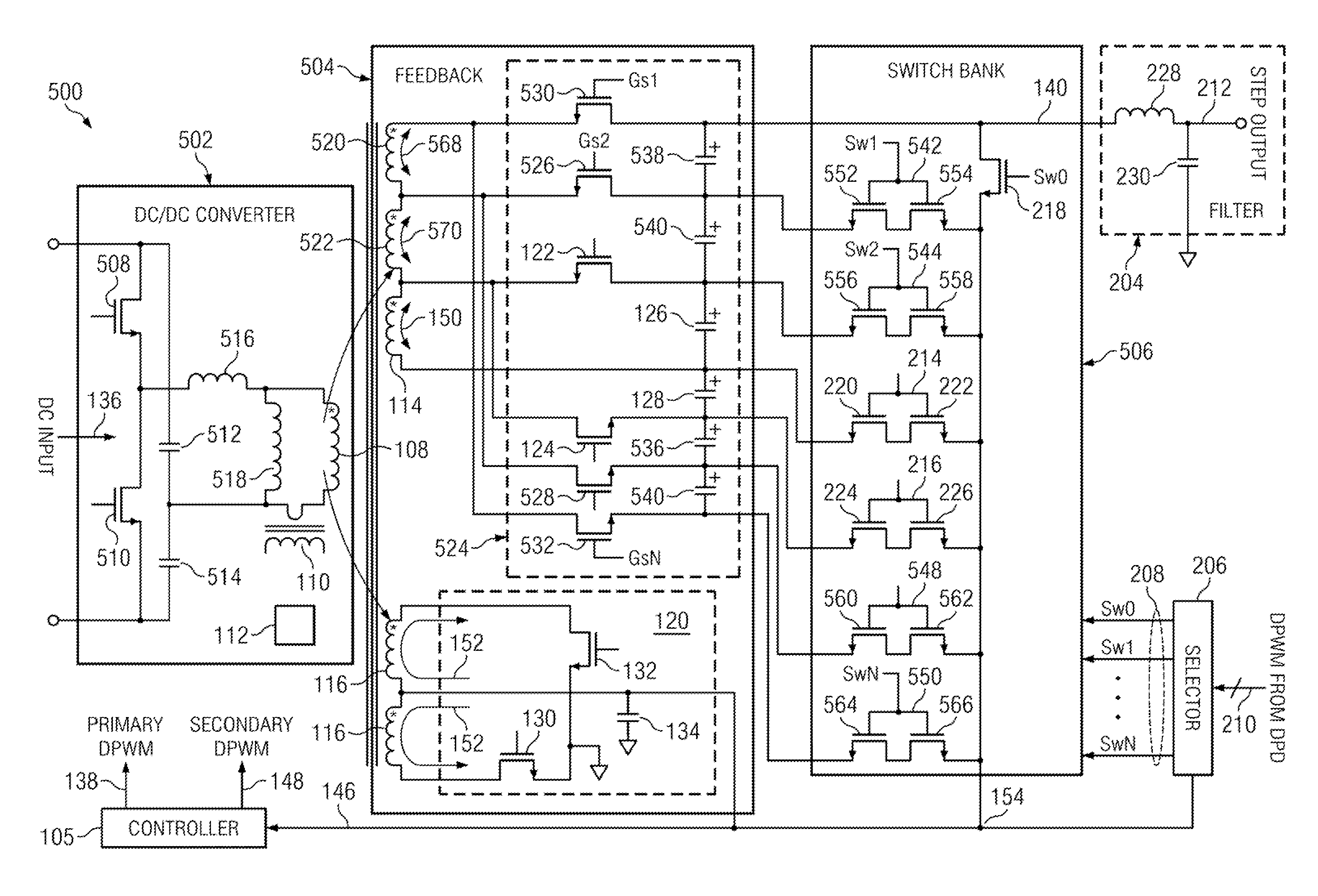
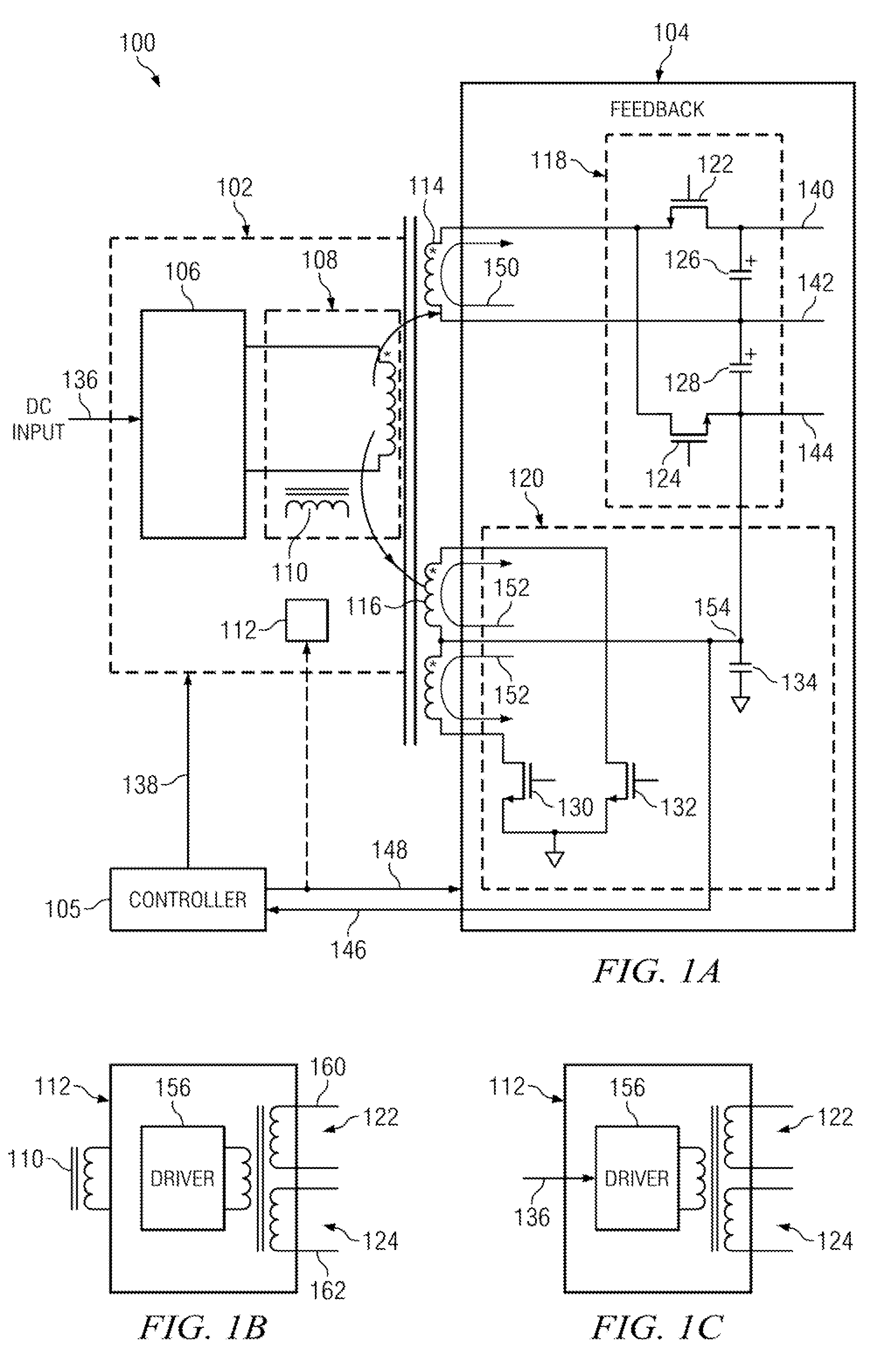
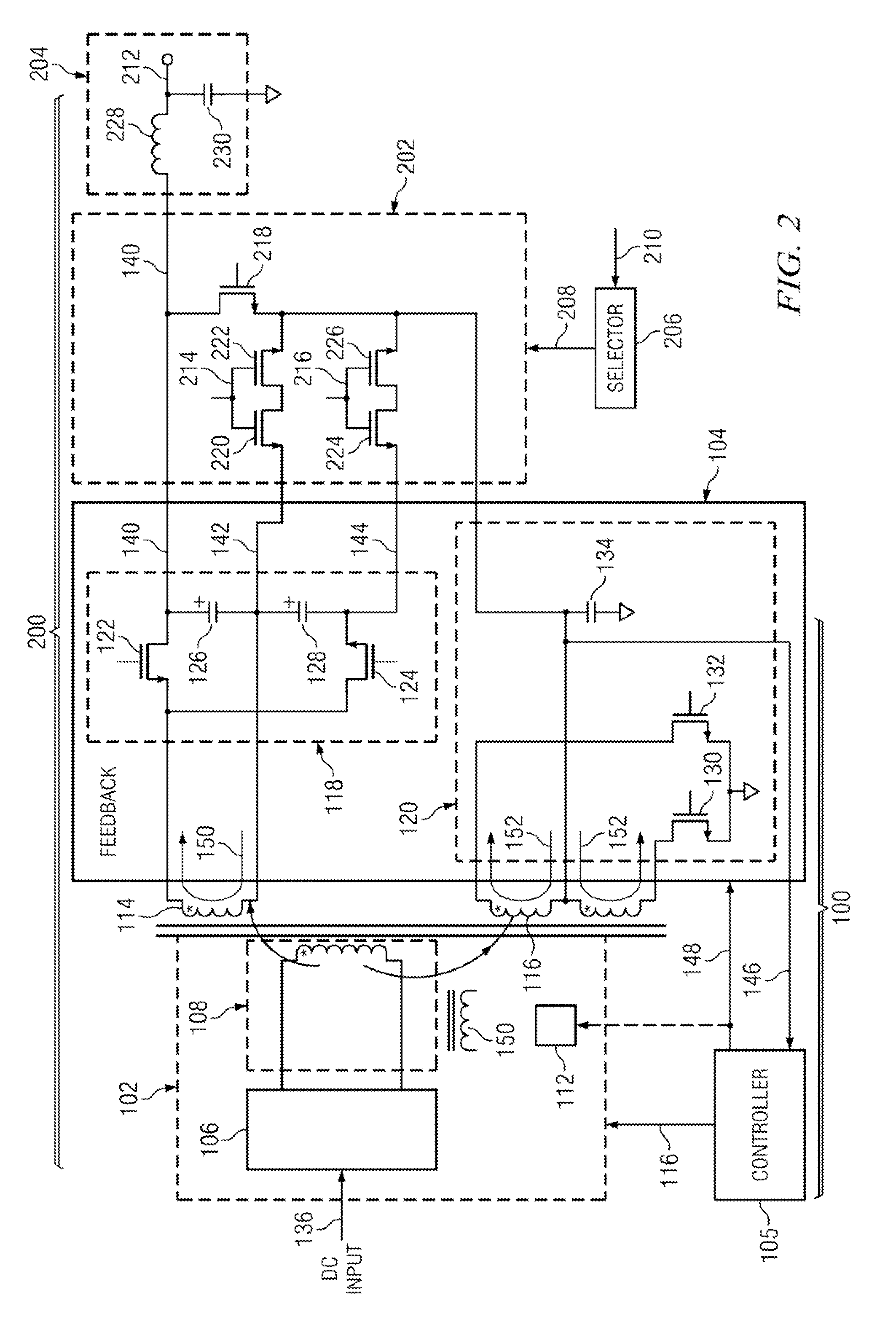
[0020]FIG. 1A illustrates an example of a DC / DC converter 100 with multiple outputs in accordance with an aspect of the present invention.

[0021]As illustrated in the figure, DC / DC converter 100 includes a primary side 102, a secondary side 104 and a controller 105. Primary side 102 includes a switching network 106, a primary winding 108, a current transformer 110 and driving portion 112. Secondary side 104 includ...


PUM


Abstract

An envelope tracking power supply has a multiple-output DC / DC converter, a switch bank, an output voltage selector and an output filter. The DC / DC converter has an alternating current generating portion and a full rectifying portion. The alternating current generating portion, typically a LC circuit, can receive an input voltage and operate at zero voltage switching. The full rectifying portion includes at least one secondary winding and one voltage doubler output. Each voltage doubler has a first transistor, a second transistor, a first capacitor and a second capacitor. The transistors used as rectifier devices allow currents to flow bi-directionally and sink and source the currents from and to output capacitors to keep their voltage balance. Secondary windings and output capacitors are connected in series respectively. A switch bank selects a desired voltage from the series connected capacitors and connects it to the output filter. The switch bank receives an envelope tracking command from the voltage selector and provides a step voltage to the output. The output voltage is changed at switching speed to track a high bandwidth envelope signal.

Description

BACKGROUND[0001]Conventional wireless systems currently have a power-conversion efficiency as low as 15%. In particular, in a conventional wireless system, an only about 15% of the input power is transmitted with the transmitted signal.[0002]Conventionally, a constant DC output voltage is used to power a wireless system to transmit a signal. The power used for transmission is only a small fraction of the total power supplied by the constant DC output power supply. The power loss, caused by inefficient operation of the power amplifier, unnecessarily heats the power amplifier's components.[0003]What is needed is an improved power supply with variable voltage output and whose output that tracks the peak voltage envelope of the power amplifier output to decrease the power amplifier power loss.BRIEF SUMMARY[0004]A system and method are provided for improving wireless system power efficiency with a variable output power supply, which tracks the envelope of the power amplifier's output to ...

Claims


Application Information

Patent Timeline
Patent Type & Authority Applications(United States)
IPC IPC(8): H02M3/335
CPCH03F1/025H03F1/3241H03F3/189H03F2200/555H03F2200/507H03F2200/511H03F3/245
Inventor YE, ZHONG
Owner TEXAS INSTR INC
Why Eureka
Try Eureka