Light-emitting element driving device

a technology of driving device and light-emitting element, which is applied in the direction of static indicating device, electroluminescent light source, instruments, etc., can solve the problems of other voltage fluctuations and failure of controller to operate incorrectly, so as to prevent operating errors, reduce power loss in the drive current generator, and continue the operation of the drive current generator

Active Publication Date: 2012-03-29
PANASONIC CORP
View PDF5 Cites 78 Cited by
  • Summary
  • Abstract
  • Description
  • Claims
  • Application Information

AI Technical Summary

Benefits of technology

[0011]The failure detector of a light-emitting element driving device according to the invention detects light-emitting element failure based on comparison of plural monitored voltages. As a result, variation in the monitored voltages resulting from variation in the drive voltage that drives the light-emitting elements can be cancelled by same-phase components, and variation in the monitored voltages caused only by a failed light-emitting element can be detected. Operating errors can therefore be prevented, and light-emitting element failures can be reliably and easily detected. Continued operation of the drive current generator can also be prevented when the monitored voltages applied to the drive circuit increase when a light-emitting element has failed. Power loss in the drive current generator can therefore be reduced, and the safety of the light-emitting element driving device can be improved.
[0012]Other objects and attainments together with a fuller understanding of the invention will become apparent and appreciated by referring to the following description and claims taken in conjunction with the accompanying drawings.
[0013]FIG. 1 is a block diagram showing the general configuration of a light-emitting element driving device according to a first embodiment of the invention.
[0014]FIG. 2 is a circuit diagram showing the specific configuration of a failure detector contained in the light-emitting element driving device according to the first embodiment of the invention.
[0015]FIG. 3 is a block diagram showing the configuration of a light-emitting element driving device according to the related art.

Problems solved by technology

However, sudden load variations in the backlight system of a television using an LCD panel can produce overshoot and other voltage fluctuations in the drive voltage output by the DC / DC converter (also called a drive voltage generator).
As a result, even though the LED is operating normally, operation of the comparator that compares the monitored voltage with the fixed reference voltage may cause the failure controller to operate incorrectly.

Method used


Image

  • Light-emitting element driving device
  • Light-emitting element driving device
  • Light-emitting element driving device

Examples


embodiment 1

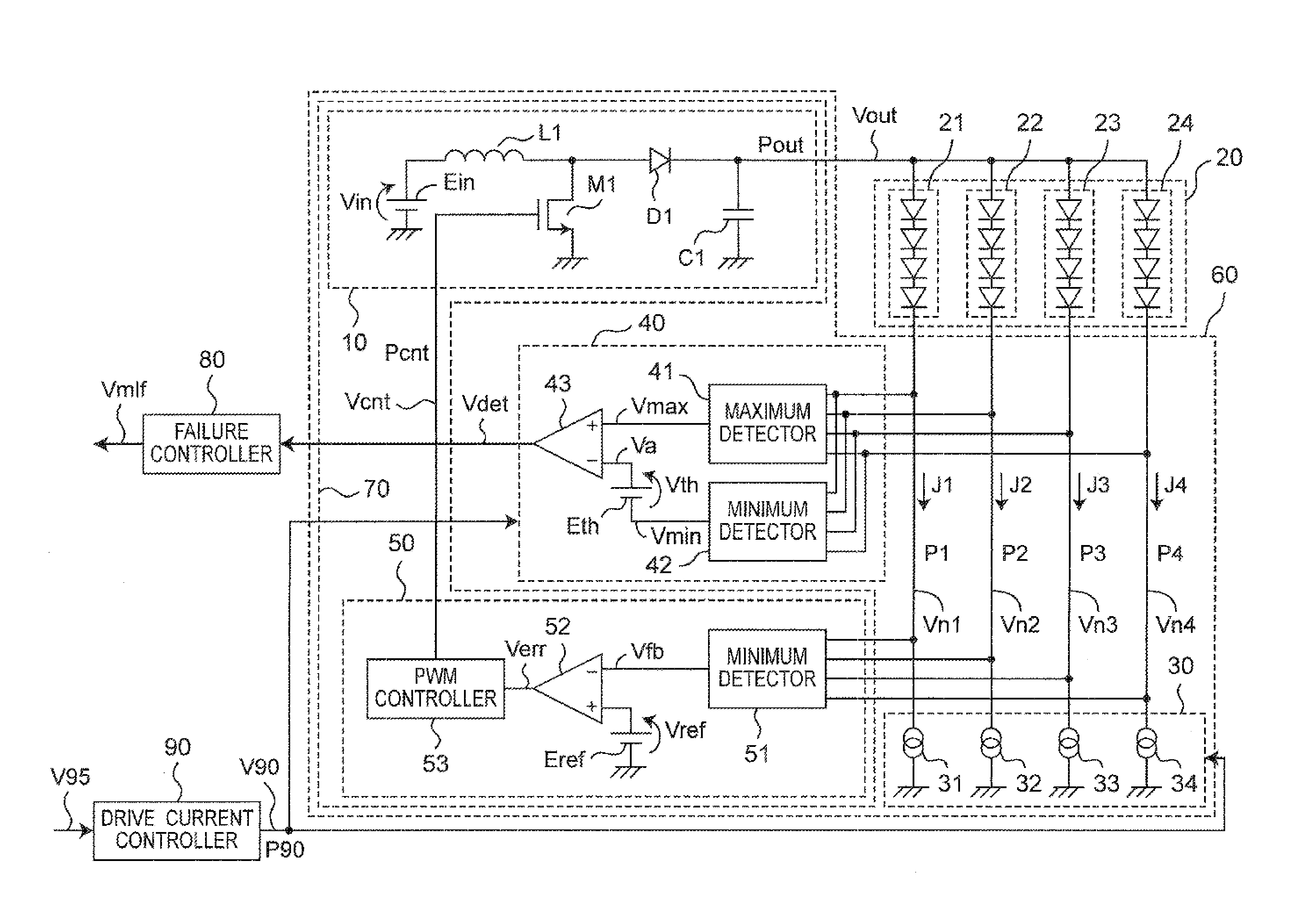
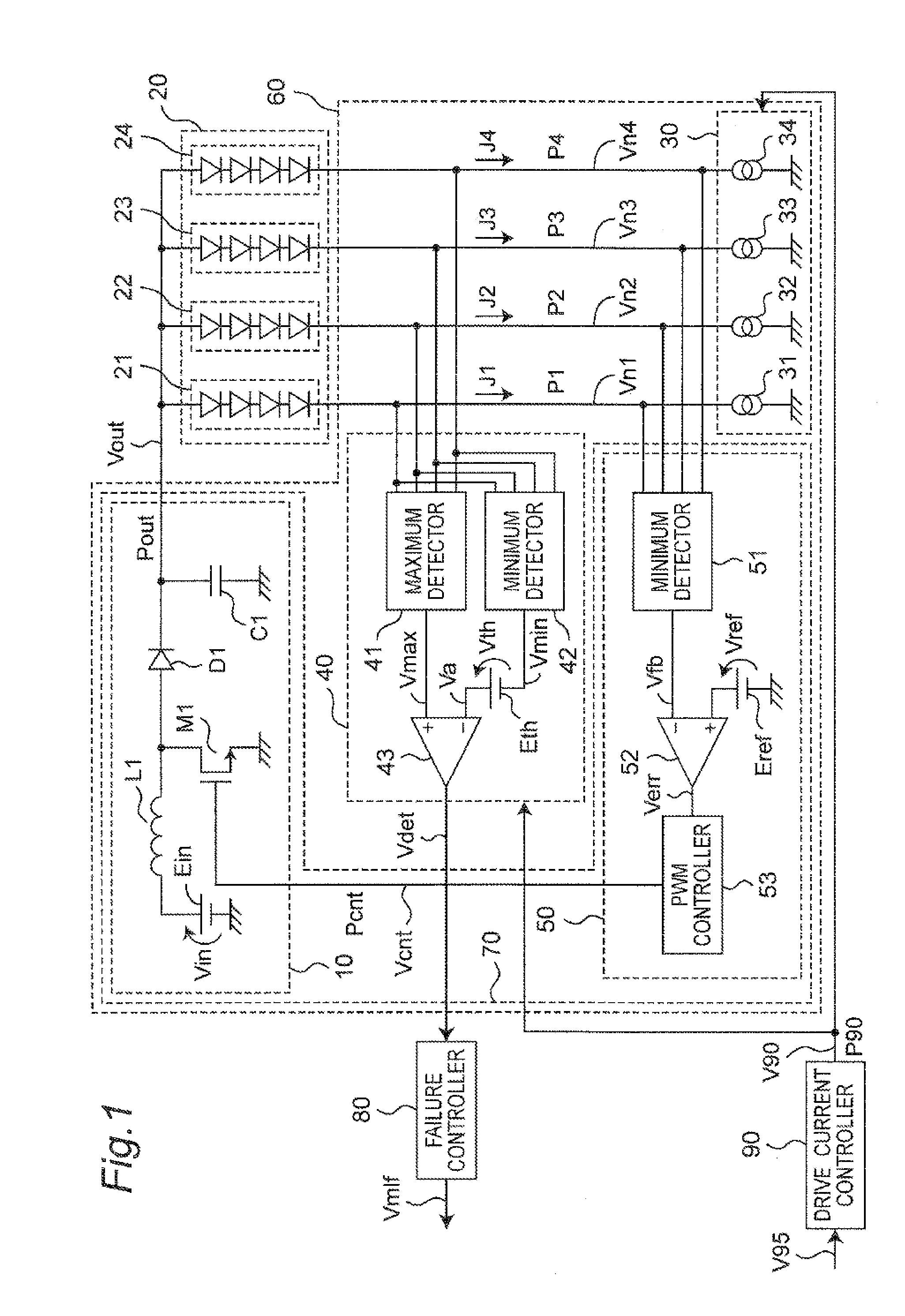
[0017]FIG. 1 is a block diagram showing the general configuration of a light-emitting element driving device 60 according to this embodiment of the invention. The light-emitting element driving device 60 includes a drive voltage generator 70, drive current generator group 30, power supply controller 50, failure detector 40, and monitoring paths P1, P2, P3, P4, and drives a light-emitting element array group 20. The drive voltage generator 70 includes the power supply controller 50, supply voltage converter 10, and control path Pcnt.

[0018]The light-emitting element array group 20 includes light-emitting element arrays 21, 22, 23, 24. Each light-emitting element array 21 to 24 has N (where N is 1 or more) light-emitting elements. The light-emitting elements in this embodiment of the invention are LEDs (light-emitting diodes), but could be light-emitting elements other than LEDs. One end of each light-emitting element array 21 to 24 is connected to the output path Pout of the supply vo...


PUM


Abstract

Short circuit failures and open circuit failures of light-emitting elements used for the backlight in an LCD panel can be reliably and easily detected. The voltage at the node between each series-connected light-emitting element array and a drive circuit is detected as a monitored voltage. A maximum detector detects the highest and a minimum detector detects the lowest of these monitored voltages. Short circuit or open circuit failure of a light-emitting element is detected by comparing the voltage difference between the maximum detector output and the minimum detector output with a specific reference voltage.

Description

CROSS-REFERENCE TO RELATED APPLICATIONS[0001]This is a continuation application of International Application No. PCT / JP2010 / 001493, filed Mar. 4, 2010 entitled “LIGHT-EMITTING ELEMENT DRIVING DEVICE” and claims priority to Japanese Patent Application No. 2009-138038 filed Jun. 9, 2009, the content of which is incorporated by reference herein.BACKGROUND OF THE INVENTION[0002](1) Field of the Invention[0003]The present invention relates to a light-emitting element driving device, and relates more particularly to a device that drives a light-emitting element such as a light-emitting diode (LED) connected to a power supply circuit.[0004](2) Description of Related Art[0005]LEDs are increasingly used for backlights in liquid crystal display (LCD) panels. When LEDs are used as a backlight for an LCD panel (LCD backlight), a specific constant current is generally supplied to a plurality of LEDs connected in series, causing them to emit light. The number of LEDs and the amount of current sup...

Claims


Application Information

Patent Timeline
Patent Type & Authority Applications(United States)
IPC IPC(8): H05B37/03H05B44/00
CPCH05B33/0815H05B33/0827H05B33/083G09G3/3406G09G2320/0233H05B33/089H05B45/46H05B45/347H05B45/52H05B45/38H05B45/48
Inventor TAKATA, GOKATAOKA, SHINICHIROYAMAMOTO, YASUNORIKAWAHARA, TSUKASAUEDA, RYUJIITOU, DAISUKE
Owner PANASONIC CORP
Why Eureka
Try Eureka