Wireless local area network (WLAN) channel radio-frequency identification (RFID) tag system and method therefor

a radio-frequency identification and local area network technology, applied in the field of wireless networks, can solve the problems of inability to support mac (medium access control) support and interface for some applications, and add additional hardware to increase the cost and complexity of locating stations, so as to avoid disrupting the operation of the wlan

Inactive Publication Date: 2005-11-08
AEROSCOUT
View PDF8 Cites 205 Cited by
  • Summary
  • Abstract
  • Description
  • Claims
  • Application Information

AI Technical Summary

Benefits of technology

[0009]The above objective providing an improved RFID tag system that does not require substantial additional hardware and / or additional frequency bands for the locating stations is achieved in a method and system. The method is embodied in a system that determines a physical location of an RFID tag. The RFID tags include a transmit-only RF module with an optional sniffer circuit that can detect the presence of traffic without receiving and decoding the WLAN signals. A second option includes a sniffer circuit that can receive and decode WLAN signals. In a preferred embodiment, the RFID tags transmit in-band WLAN signals bearing a fictitious address that does not correspond to an address of a unit within the WLAN. The signals are transmitted periodically at predetermined intervals and avoid disrupting the operation of the WLAN by transmitting either after a sniffer circuit determines that no other transmissions are in progress or using a proprietary PN code sequence or preamble differing from standard WLAN signals. The location units and master station for receiving the above-described transmissions may be specially modified to receive the fictitious address and proprietary PN code sequence or preambles.

Problems solved by technology

The additional hardware increases the cost and complexity of the locating stations.
However, the complexity of a full WLAN unit including a network receiver, full MAC (Medium Access Control) support and interface is not justified for some applications in which a low-cost RFID tag is desirable.
For example, employee badges and inventory tags do not require a full WLAN unit including a full receiver, transmitter and network support that generally will not be cost-justified for these applications.

Method used


Image

  • Wireless local area network (WLAN) channel radio-frequency identification (RFID) tag system and method therefor
  • Wireless local area network (WLAN) channel radio-frequency identification (RFID) tag system and method therefor
  • Wireless local area network (WLAN) channel radio-frequency identification (RFID) tag system and method therefor

Examples


Embodiment Construction

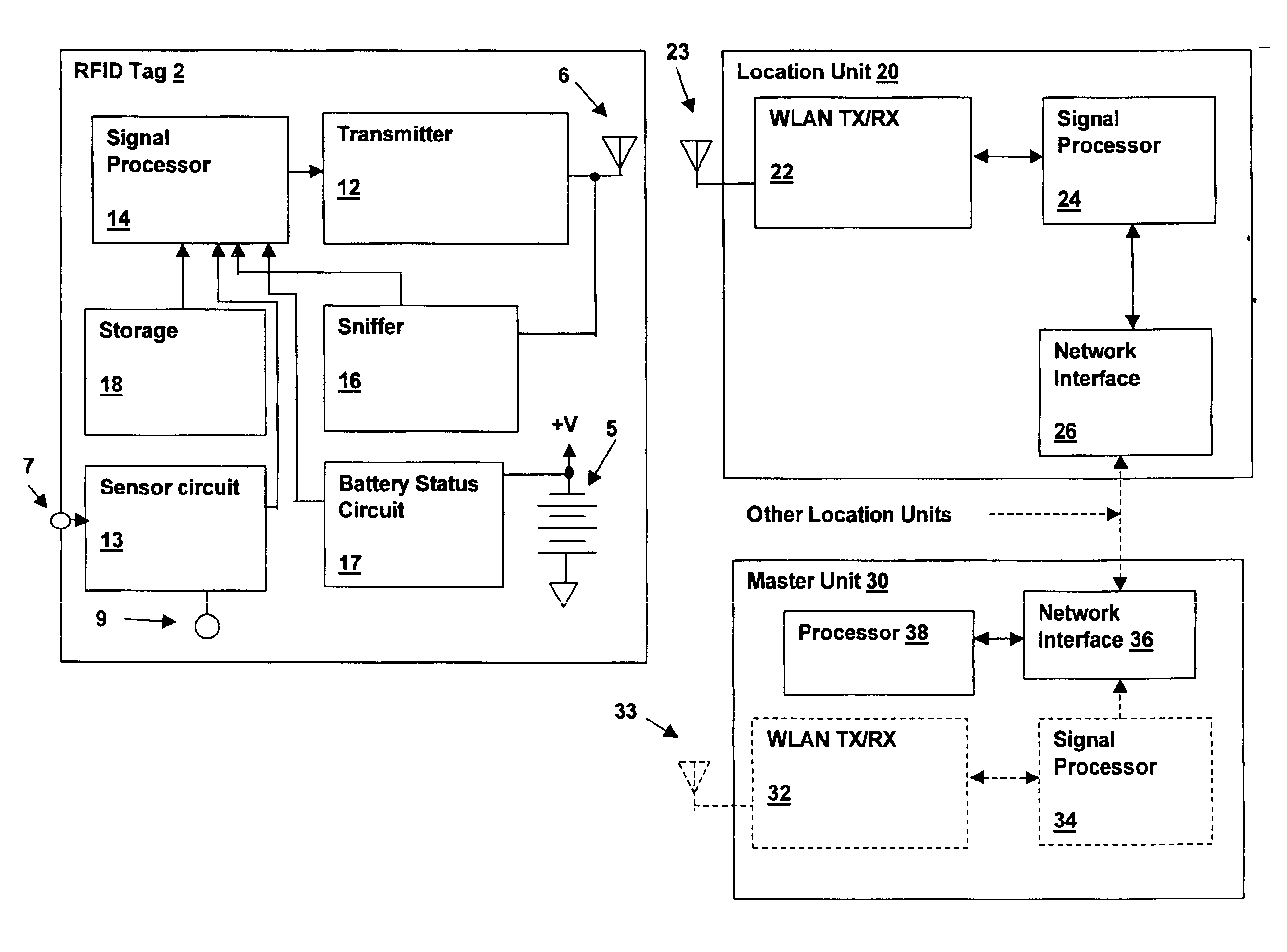
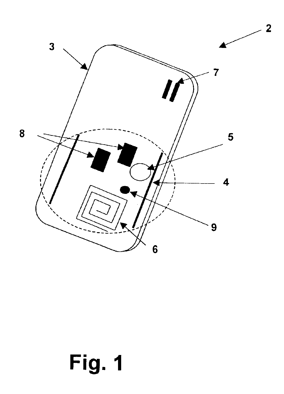
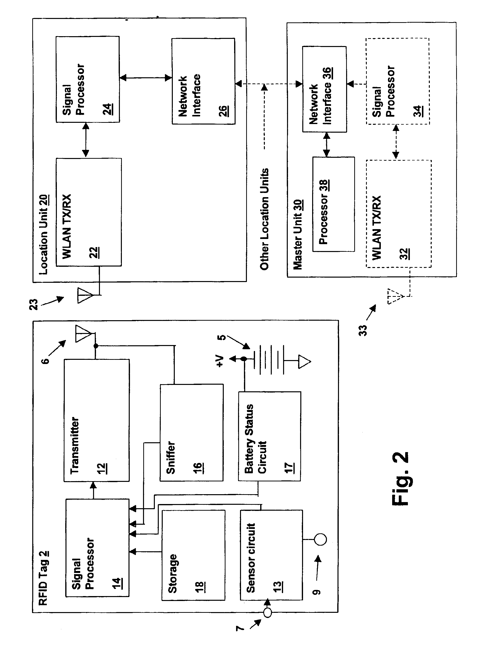
[0014]Referring to the figures, and in particular to FIG. 1, a radio-frequency identification (RFID) tag 2, is depicted in accordance with an embodiment of the present invention. Tag 2 includes a printed circuit substrate 4 on which electronic components 8 are interconnected via conductive patterns on substrate 4 to form the tag circuits. The circuits generally comprise a transmitter for transmitting a signal on a wireless local area network (WLAN) channel, for reception by location units coupled to a WLAN. A battery 5 supplies power to the electronic circuit. An antenna 6 is coupled to the transmitter for launching the transmitted WLAN channel signal for reception by location units. Substrate 4 and electronic components 8 are covered with a housing 3, which may include surface decoration forming an identification badge, apertures through the housing for attachment to key rings or cords for using tag as a pendant, etc. A sensor 9 may be included within housing for measuring characte...


PUM


Abstract

A wireless local area network (WLAN) radio-frequency identification (RFID) tag system provides location finding in a wireless local area network (WLAN), using a WLAN channel. Interference with the WLAN is prevented by either using a sniffer circuit to determine that no network transmission is in progress, using a modified coding sequence or preamble to cause standard WLAN receivers to ignore the RFID tag transmissions, or transmitting a message using a standard WLAN signal addressed to an address not corresponding to a unit within the WLAN. Location units (LUs) and a master unit (MU) within the WLAN receive the RFID tag transmissions and can determine the location of a tag by triangulation based on differences between the signals received at the location units from the tag. The master unit receives the signal information from the location units and computes the location of the tag. Time-difference-of-Arrival (TDOA), received signal strength indication (RSSI) or other triangulation techniques may be used.

Description

CROSS-REFERENCE TO RELATED APPLICATIONS[0001]The present application is related to previously-filed United States patent applications assigned to the same assignee: “METHOD AND APPARATUS FOR ENHANCING SECURITY IN A WIRELESS NETWORK USING DISTANCE MEASUREMENT TECHNIQUES”, Ser. No. 10 / 156,244, filed May 24, 2002; “METHOD AND APPARATUS FOR INTRUSION MANAGEMENT IN A WIRELESS NETWORK USING PHYSICAL LOCATION DETERMINATION”, Ser. No. 10 / 171,427, filed Jun. 13, 2002; and “METHOD AND SYSTEM FOR LOCATION FINDING IN A WIRELESS LOCAL AREA NETWORK”, Ser. No. 10 / 225,267, filed Aug. 20, 2002. The specifications of the above-referenced U.S. patent applications are herein incorporated by reference.BACKGROUND OF THE INVENTION[0002]1. Field of the Invention[0003]The present invention relates generally to wireless networks, and more specifically, to a radio-frequency identification tag and system for determining the physical location of tagged items.[0004]2. Background of the Invention[0005]Radio-frequ...

Claims


Application Information

Patent Timeline
Patent Type & Authority Patents(United States)
IPC IPC(8): G01S13/00G01S13/87G01S5/06G01S13/76H04W64/00H04W72/08H04W84/12
CPCG01S5/06G01S13/878G01S13/765
Inventor ALJADEFF, DANIELGRANOT, YAIRTSRUYA, SHALOMAMSALEM, REUVEN
Owner AEROSCOUT
Why Eureka
Try Eureka