Display device and a method of driving the same
- Summary
- Abstract
- Description
- Claims
- Application Information
AI Technical Summary
Benefits of technology
Problems solved by technology
Method used
Image
Examples
first embodiment
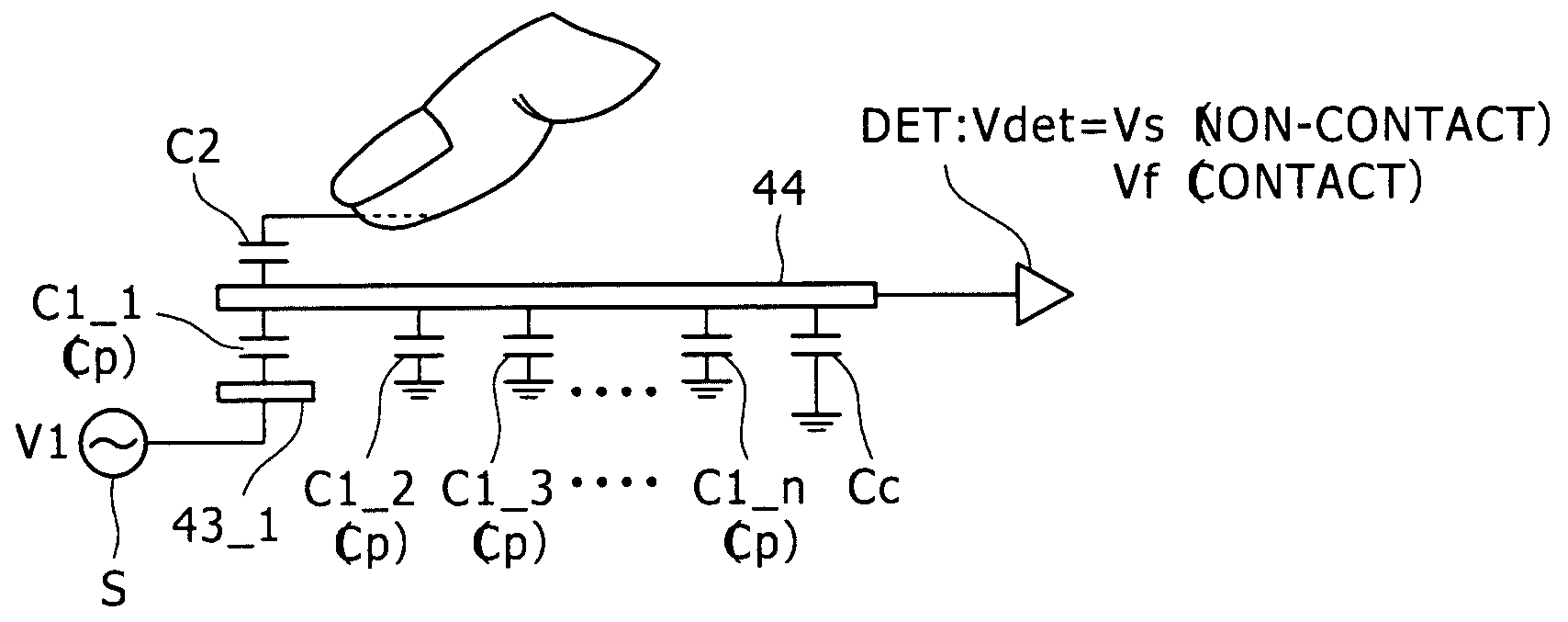
[0048]FIGS. 4A to 4C respectively show top plan views specialized in dispositions of electrodes, and a circuit or driving or detecting the electrode in the display device according to the first embodiment. Also, FIG. 4D shows a schematic cross sectional view of a structure of the display device according to the first embodiment. FIG. 4D shows a cross section for six pixels, for example, in a row direction (in a pixel display line direction). FIG. 5 is an equivalent circuit diagram of a pixel. The display device illustrated in FIGS. 4A to 4D is a liquid crystal display device including a liquid crystal layer as “a display functional layer.”
[0049]The liquid crystal display device 1, as previously stated, has an electrode (counter electrode). In this case, this counter electrode is a common electrode, common to a plurality of pixels, of two electrodes facing to each other so as to hold the liquid crystal layer between them. Also, a common drive signal Vcom giving a signal voltage for g...
second embodiment
[0086]Next, a second embodiment of the present invention will be described in detail with reference to FIG. 10, FIGS. 11A and 11B, and FIGS. 12A and 12B. In the second embodiment, unlike the case of the first embodiment described above, a liquid crystal element having a transverse electric field mode is used as the display element.
[0087]FIG. 10 is a schematic cross sectional view showing a structure of the liquid crystal display device according to the second embodiment of the present invention. In FIG. 10, portions corresponding to those in the first embodiment are designated with the same reference numerals, respectively, and a description thereof is suitably omitted here for the sake of simplicity.
[0088]The display device of the second embodiment is different exclusively to positions of the electrodes (having the different patterns) from the display device of the first embodiment in that the counter electrodes 43 are disposed on the drive substrate 2 side. The counter electrodes ...
third embodiment
[0098]A third embodiment provides another driving method which can be applied to the liquid crystal display device having any of the structures of the first and second embodiments described above.
[0099]FIG. 14 shows a method of A.C. driving the counter electrodes according to the third embodiment of the present invention. FIG. 14 is illustrated instead of FIGS. 8A to 8C. Thus, other figures, that is, FIGS. 4A to 4D to FIG. 13 can be applied to the third embodiment as well. However, in each of the first embodiment and second embodiment (including Changes 1 and 2 as well) described above, the Vcom driving circuit 9 and the A.C. signal source S shown in FIGS. 4A to 4D, FIGS. 6A and 6B, FIGS. 7A and 7B, etc. select a plurality of counter electrodes 43 (the A.C. drive electrode unit EU) to be A.C. driven by using one or more predetermined pixel display lines (write unit) as a unit. On the other hand, in the third embodiment, a pitch length (a sum of a width of the counter electrode and a...
PUM
 Abstract
Description
Claims
Application Information
 - R&D
- Intellectual Property
- Life Sciences
- Materials
- Tech Scout
- Unparalleled Data Quality
- Higher Quality Content
- 60% Fewer Hallucinations
Browse by: Latest US Patents, China's latest patents, Technical Efficacy Thesaurus, Application Domain, Technology Topic, Popular Technical Reports.
© 2025 PatSnap. All rights reserved.Legal|Privacy policy|Modern Slavery Act Transparency Statement|Sitemap|About US| Contact US: help@patsnap.com


