
Power Supply System for Vehicle with Improved Energy Efficiency and Vehicle Including the Same

a technology of power supply system and vehicle, which is applied in the direction of propulsion parts, propulsion using engine-driven generators, electric devices, etc., can solve the problems of poor power conversion efficiency and the addition of dedicated power converters, and achieve the effects of reducing power loss, transmission and reception, and small siz

Inactive Publication Date: 2007-11-29
TOYOTA JIDOSHA KK
View PDF13 Cites 76 Cited by
  • Summary
  • Abstract
  • Description
  • Claims
  • Application Information

AI Technical Summary

Benefits of technology

[0032] Therefore, a primary advantage of the present invention is that power loss can be reduced because transmission and reception of the power between two rotating electric machines is more direct.
[0033] In addition, another advantage of the present invention is that the vehicle can have a smaller size because the dedicated power converter is not necessary.

Problems solved by technology

In this manner, a path to transmit the power from motor-generator MG1 through inverters 537, 536 to motor-generator MG2 passes through the inverter twice, which results in poor power conversion efficiency.
That is, there is a disadvantage that the dedicated power converter should additionally be provided in order to output the commercial power supply of AC 100V from the hybrid vehicle.

Method used


Image

  • Power Supply System for Vehicle with Improved Energy Efficiency and Vehicle Including the Same
  • Power Supply System for Vehicle with Improved Energy Efficiency and Vehicle Including the Same
  • Power Supply System for Vehicle with Improved Energy Efficiency and Vehicle Including the Same

Examples


first embodiment

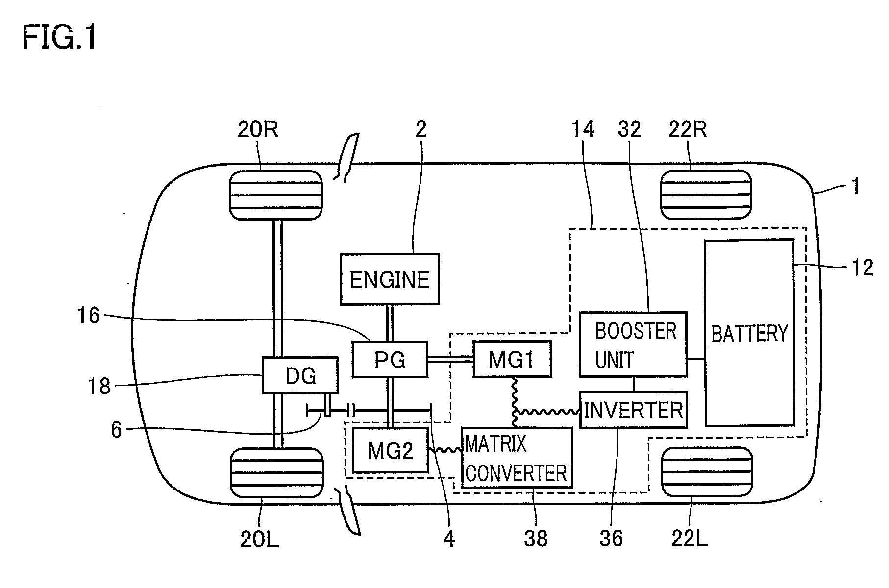
[0044]FIG. 1 is a schematic diagram showing a configuration of a hybrid vehicle 1 according to a first embodiment.

[0045] Referring to FIG. 1, hybrid vehicle 1 includes front wheels 20R, 20L, rear wheels 22R, 22L, an engine 2, a planetary gear 16, a power supply system for a vehicle 14, a differential gear 18, and gears 4, 6.

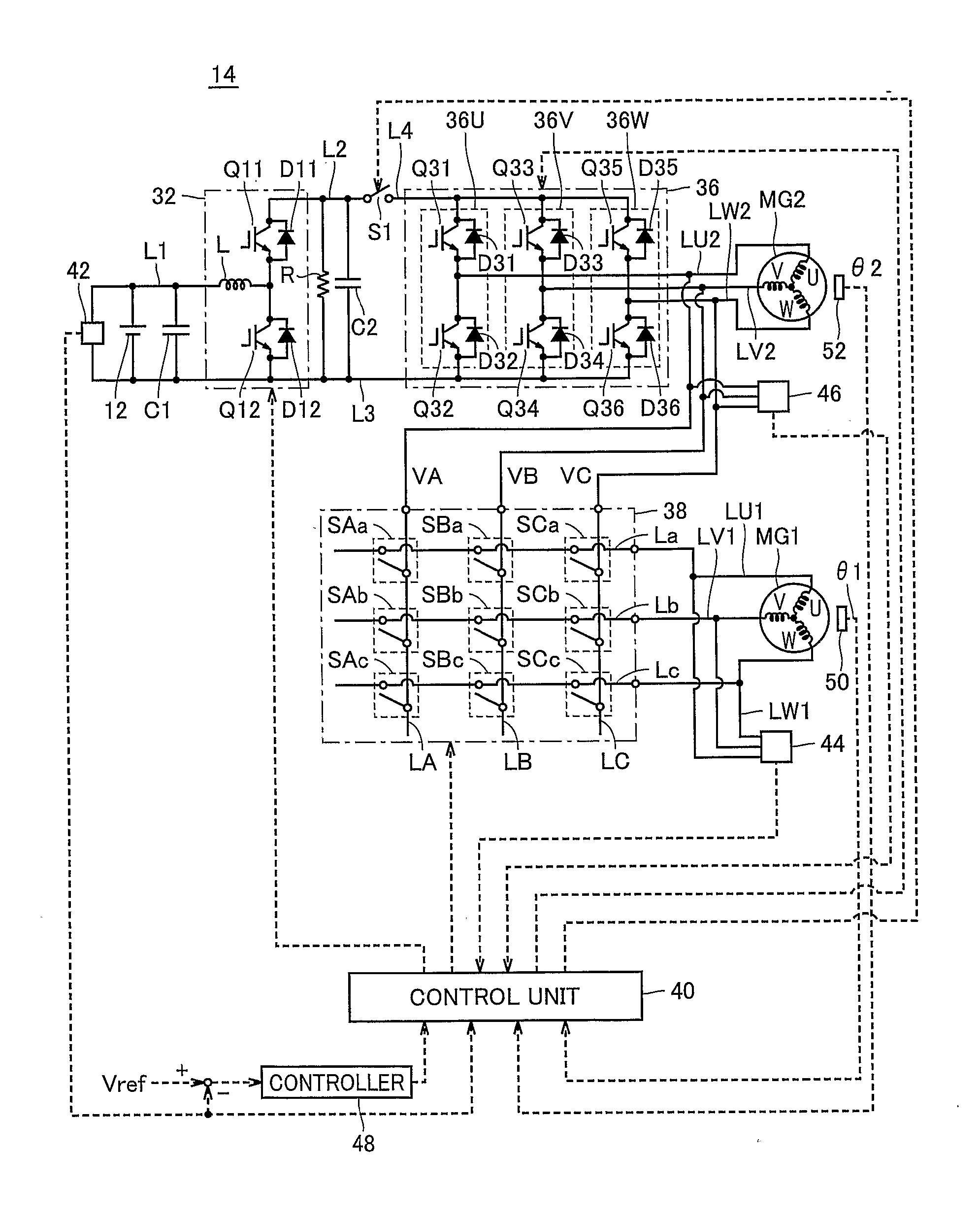
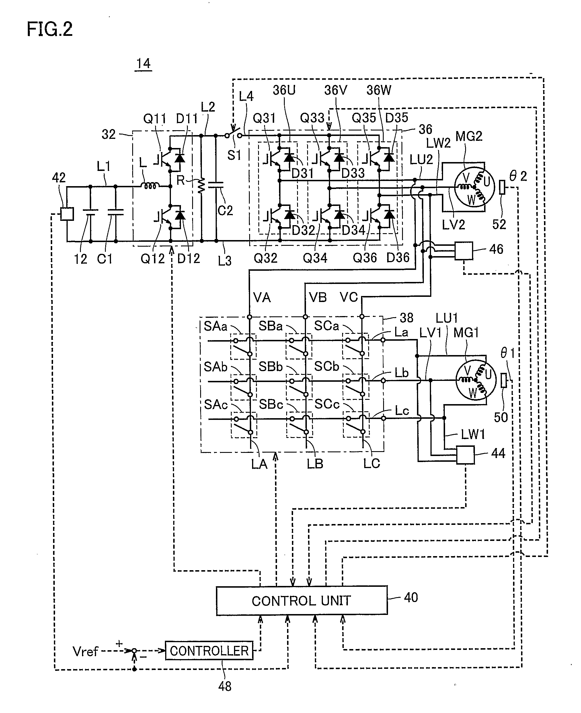
[0046] Power supply system for a vehicle 14 includes a battery 12 disposed in the rear of the vehicle, a booster unit 32 boosting DC power output from battery 12, an inverter 36 transmitting / receiving the DC power to / from booster unit 32, motor-generator MG1 generating power upon receiving the mechanical power of engine 2 through planetary gear 16, motor-generator MG2 having a rotation shaft connected to planetary gear 16, and a matrix converter 38 connected to motor-generators MG1, MG2 and inverter 36 and performing AC-AC conversion.

[0047] Planetary gear 16 has first to third rotation shafts. The first rotation shaft is connected to engine 2, the second rotat...

second embodiment

[0116]FIG. 8 is a circuit diagram showing a configuration of a power supply system for a vehicle 114 according to a second embodiment.

[0117] Referring to FIG. 8, a configuration of power supply system for a vehicle 114 is different from that of power supply system for a vehicle 14 described in connection with FIG. 2 in that a switch S2 is provided between lines LU2, LV2 and lines LA, LB and an output socket 122 for AC 100V is connected between switch S2 and lines LA, LB.

[0118] In addition, a switch S3 is provided between lines LU1, LV1 and lines La, Lb and an input socket 124 for AC 100V is connected between switch S3 and lines LA, LB. These are differences between power supply system for a vehicle 114 in FIG. 8 and power supply system for a vehicle 14 in FIG. 2. Power supply system for a vehicle 114 is otherwise the same as power supply system for a vehicle 14, and description thereof will not be repeated.

[0119] Power supply system for a vehicle 114 can use the vehicle as a powe...


PUM


Abstract

A matrix converter (38) converts three-phase AC power input from a first motor-generator (MG1) directly to three-phase AC power for driving a second motor-generator (MG2) and outputs the resultant three-phase AC power, without rectifying the three-phase AC power generated by the first motor-generator (MG1) once to DC power as in an example using a conventional three-phase full-wave rectification inverter. In a power supply system for a vehicle (14), the three-phase AC power is transmitted and received between two motor-generators (MG1, MG2) more directly, by means of the matrix converter (38). Therefore, power loss can be reduced, as compared with a conventional example in which the three-phase AC power is once converted to DC power. Thus, a power supply system for a vehicle with improved energy efficiency and a vehicle including the same can be provided.

Description

TECHNICAL FIELD [0001] The present invention relates to a power supply system for a vehicle and a vehicle including the same, and more particularly to a power supply system for a vehicle employing a matrix converter performing AC (alternate current)-AC conversion as well as a vehicle including the same. BACKGROUND ART [0002] With growing interest in energy saving and environmental issues in recent days as a backdrop, much attention has been paid to a hybrid vehicle. The hybrid vehicle has already been put into practical use and commercially available. [0003] The hybrid vehicle is a vehicle having a DC (direct current) power supply, an inverter, and a motor driven by the inverter as a power source, in addition to an engine serving as a conventional internal combustion engine. That is, the hybrid vehicle obtains the mechanical power source not only by driving the engine but also by converting a DC voltage from a DC power supply to an AC voltage using an inverter, so as to rotate the m...

Claims


Application Information

Patent Timeline
Patent Type & Authority Applications(United States)
IPC IPC(8): H02M5/45B60K6/445B60W20/00B60L11/00B60L50/16B60W10/08H02M5/27H02M5/297
CPCB60K6/26Y02T10/6239B60L11/005B60L11/123B60L11/14B60L11/1816B60L11/1877B60L15/007B60L2210/20B60L2220/14B60W10/08H02M5/297H02P5/747Y02T10/6217Y02T10/644Y02T10/7005Y02T10/7022Y02T10/705Y02T10/7077Y02T10/725Y02T90/127Y02T90/14B60K6/445Y02T10/7072B60L53/14B60L50/40B60L50/61B60L50/16B60L50/66Y02T10/62Y02T10/64Y02T10/70Y02T10/72Y02T90/12
Inventor OYOBE, HICHIROSAIISHIKAWA, TETSUHIRO
Owner TOYOTA JIDOSHA KK
Learn More