Device and method for gas turbine unlocking

a gas turbine and device technology, applied in the ignition of turbine/propulsion engines, engine starters, combustion air/fuel air treatment, etc., can solve the problem of not addressing the arrangement of unlocking gas turbines, and achieve the effect of reducing the time required to unlock and reducing downtim

Active Publication Date: 2017-12-19
NUOVO PIGNONE TECH SRL
View PDF37 Cites 72 Cited by
  • Summary
  • Abstract
  • Description
  • Claims
  • Application Information

AI Technical Summary

Benefits of technology

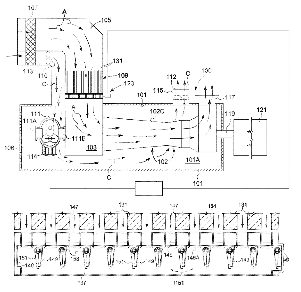
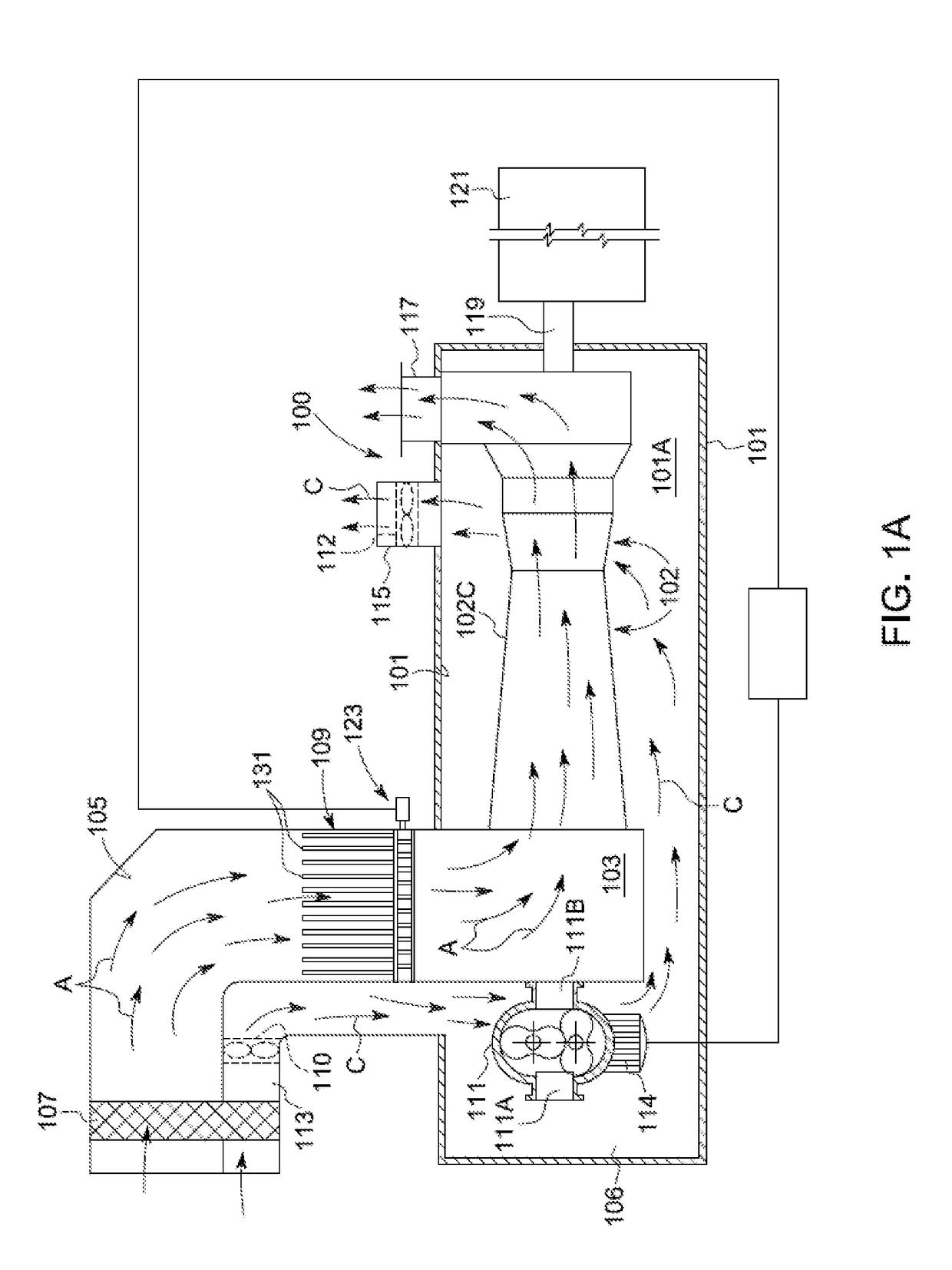
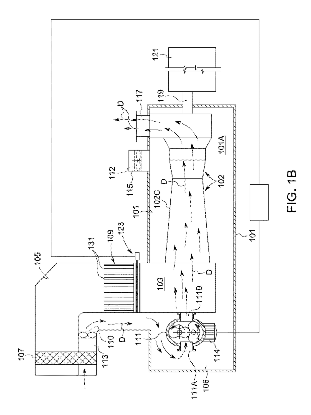
[0006]To reduce the downtime required to cool down the gas turbine following shut-down and locking, a forced air-stream generator is provided which generates a stream of forced cooling air at a pressure sufficient to circulate the cooling air throughout the gas turbine when the latter is in a locked mode. The forced air stream reduces the time required to unlock the turbine rotor, so that the gas turbine can be re-started after a substantially shorter time interval than when no forced cooling air is provided.
[0014]To achieve a better closure of the air intake plenum, and therefore a more efficient forced cooling of the gas turbine, at least some, and, in an embodiment, each, air outlet aperture is at least partly surrounded by a sealing gasket co-acting with the respective shutter. In some embodiments, each air outlet aperture is entirely surrounded by a sealing gasket. The sealing gasket may have a self-sealing shape. A self-sealing shape is one which increases the sealing effect when the air pressure in the air intake plenum increases.
[0017]In some embodiments an end-stop may be provided for each air outlet opening, said end-stop defining a closing position of the respective shutter, so that the pressure inside the air intake plenum will not squeeze the sealing gasket. This prevents mechanical damage to the sealing gasket.

Problems solved by technology

This prior art arrangement does not address the problem of unlocking a gas turbine after shut-down, however.

Method used


Image

  • Device and method for gas turbine unlocking
  • Device and method for gas turbine unlocking
  • Device and method for gas turbine unlocking

Examples


Embodiment Construction

[0032]The following detailed description of the exemplary embodiments refers to the accompanying drawings. The same reference numbers in different drawings identify the same or similar elements. Additionally, the drawings are not necessarily drawn to scale. Also, the following detailed description does not limit the invention. Instead, the scope of the invention is defined by the appended claims.

[0033]Reference throughout the specification to “one embodiment” or “an embodiment” or “some embodiments” means that the particular feature, structure or characteristic described in connection with an embodiment is included in at least one embodiment of the subject matter disclosed. Thus, the appearance of the phrase “in one embodiment” or “in an embodiment” or “in some embodiments” in various places throughout the specification is not necessarily referring to the same embodiment(s). Further, the particular features, structures or characteristics may be combined in any suitable manner in one...


PUM


Abstract

An aeroderivative gas turbine including an air intake plenum; a compressor with a compressor air intake in fluid communication with the air intake plenum; a combustor; a high pressure turbine; a power turbine. A forced air-stream generator is arranged in fluid communication with the air intake plenum. A shutter arrangement is provided in a combustion-air flow path, arranged and controlled to close the combustion-air flow path for pressurizing said air intake plenum by means of the forced air-stream generator to a pressure sufficient to cause pressurized air to flow through the aeroderivative air turbine.

Description

FIELD OF THE INVENTION[0001]The present disclosure relates generally to gas turbines, particularly, to aeroderivative gas turbines. More specifically, the present disclosure relates to devices and methods for unlocking a gas turbine, following the shut-down and rotor locking due to temperature differentials inside the turbomachinery.DESCRIPTION OF THE RELATED ART[0002]Aeroderivative gas turbines are widely used as power sources for mechanical drive applications, as well as in power generation for industrial plants, pipelines, offshore platforms, LNG applications and the like.[0003]The gas turbine can be subject to shut-down, e.g. in emergency situations, and re-started after a brief time period. When the rotor of the turbine is left motionless upon shut-down, thermal deformations may occur with the reduction or elimination of clearances between rotor and stator parts, hence leading to a rubbing between rotor and stator parts or a rising up to rotor locking phenomena. Thermal deforma...

Claims


Application Information

Patent Timeline
Patent Type & Authority Patents(United States)
IPC IPC(8): F02C7/04F02C7/26F01D19/02F01D17/14F01D25/12F04D25/14F04D29/66F02C7/18F01D25/34F02C7/27
CPCF02C7/18F01D17/148F01D19/02F01D25/12F01D25/34F02C7/26F04D25/14F04D29/664F04D29/665F02C7/04F05D2260/964F02C7/27Y02T50/60F01D17/146F02C7/045F02C7/042
Inventor BETTI, TOMMASOBALDASSARRE, ANTONIOVITI, FILIPPOMEUCCI, STEFANOLAZZERI, MARCOMERLO, ROBERTOMARCUCCI, DANIELE
Owner NUOVO PIGNONE TECH SRL
Why Eureka
Try Eureka