Method and apparatus for directing solar energy to solar energy collecting cells

a technology for solar energy and collecting cells, applied in the direction of pv power plants, hybrid energy generation, thermal power plants, etc., can solve the problems of limited use of solar panels and often limited space limitations in a particular location, and achieve the effect of enhancing solar energy

Inactive Publication Date: 2000-07-11
MUSKATEVC MARK S
View PDF14 Cites 56 Cited by
  • Summary
  • Abstract
  • Description
  • Claims
  • Application Information

AI Technical Summary

Benefits of technology

It is a further object of the present invention to provide a photovoltaic array wherein solar energy is enhanced and redirected onto solar cells.

Problems solved by technology

However, because of the relatively low power output of such systems, their use has been generally limited to such remote applications as control systems, small electric motors and lighting in remote areas where conventional energy sources are not readily available.
However, in many such applications, space limitations often limit the number of panels that can be employed in a particular location.

Method used


Image

  • Method and apparatus for directing solar energy to solar energy collecting cells
  • Method and apparatus for directing solar energy to solar energy collecting cells
  • Method and apparatus for directing solar energy to solar energy collecting cells

Examples


Embodiment Construction

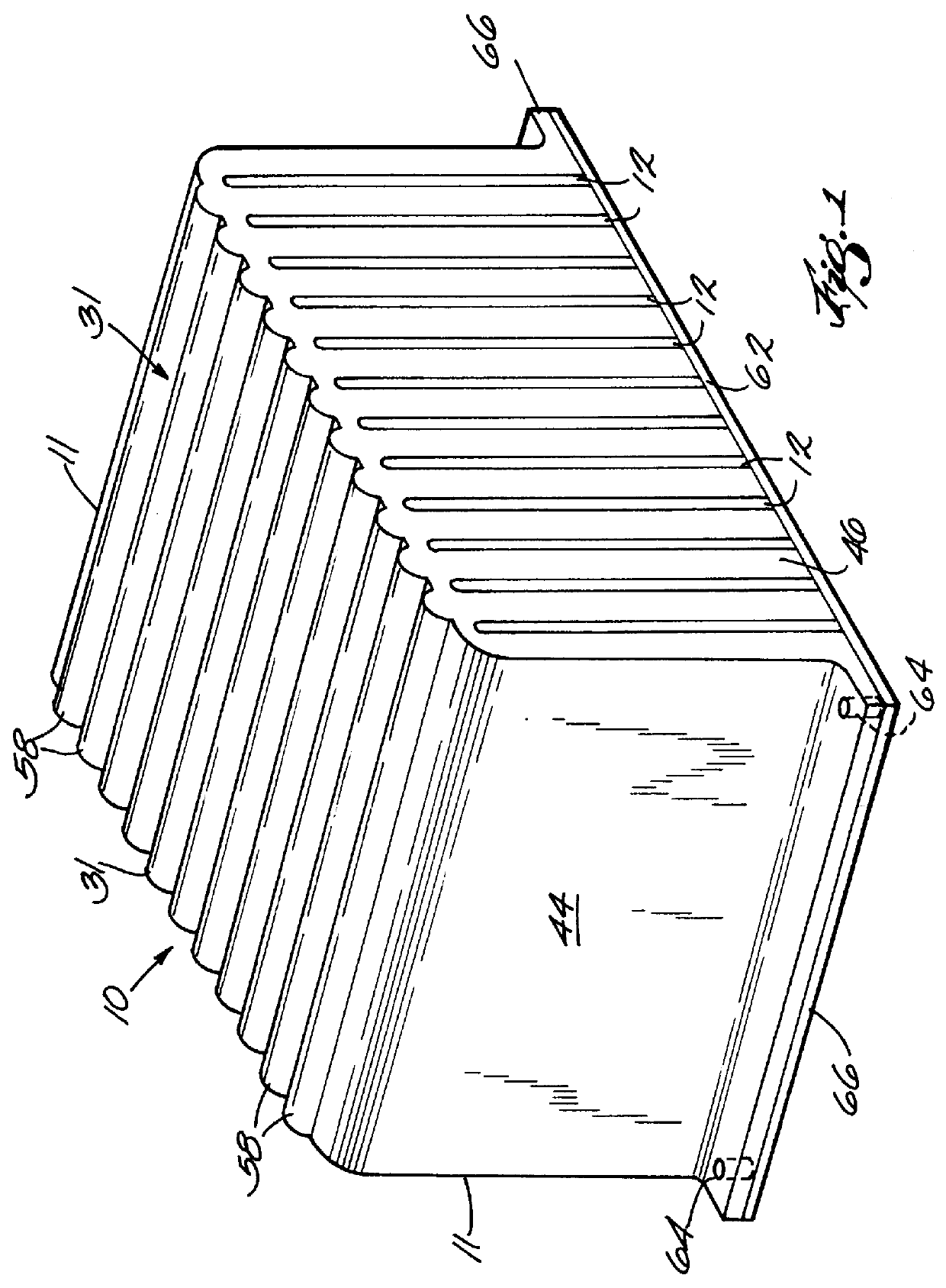
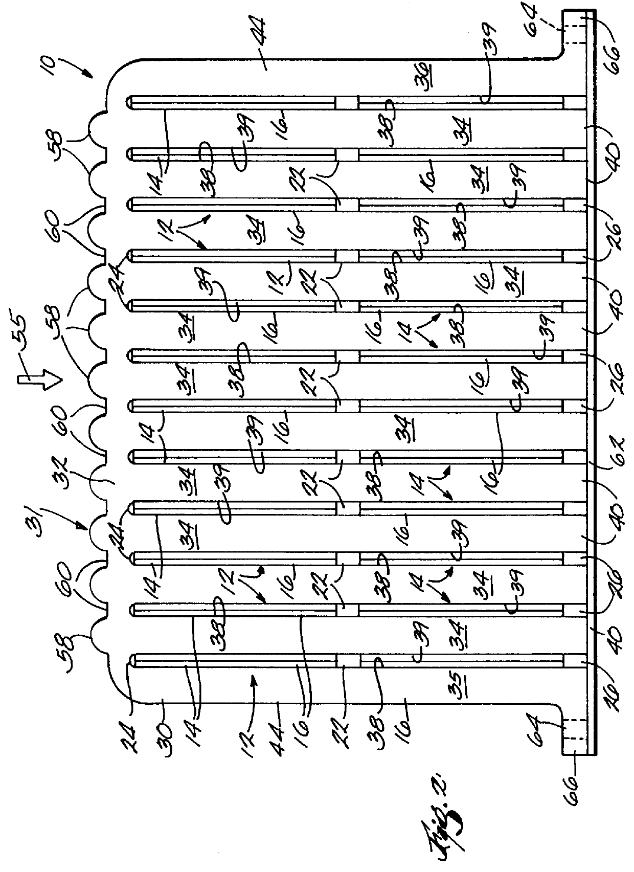
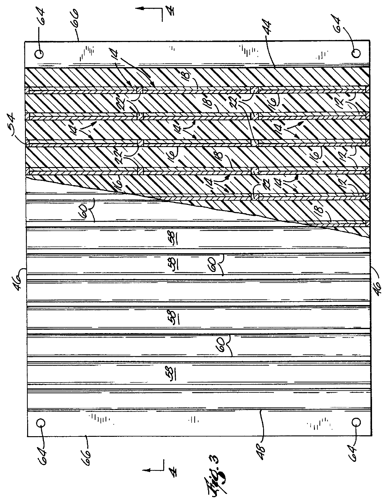
In general terms, the invention comprises a photovaltaic array including a plurality of photovaltaic cells arranged in panels and a solar energy or light collecting body having a solar energy or light collecting surface adapted to be oriented for receiving solar energy or light in a direction which defines a nominal solar energy direction. The panels are arranged in an array which extends in a direction perpendicular to the nominal solar energy direction and the panels are oriented on the light collecting body at an angle of less than 90.degree. relative to the nominal solar energy direction. In the embodiment shown in FIGS. 1-4, the panels are generally parallel to the nominal solar energy direction or, in other words, at an angle of 0.degree.. In the embodiment shown in FIGS. 5-9, the panels are oriented at an acute angle relative to the light source direction and in the embodiment of FIG. 10, the panels are arranged at an angle between the embodiment of FIGS. 1-4 and the embodime...


PUM


Abstract

A photovoltaic array includes a plurality of generally planar cells, arranged in panels, a light collecting body having a solar energy collecting surface adapted to be oriented for receiving solar energy in a nominal direction which defines a nominal light source direction. The panels are spaced apart from each other in a direction perpendicular to the nominal light source direction and each has an active surface oriented on the body at an angle of less than 90 DEG relative to the nominal light source direction. The light collecting body is transmissive for redirecting light received on the light collecting surface onto the active surfaces of the panels.

Description

This invention relates to photovoltaic cells and more particularly to a high efficiency photovoltaic cell.BACKGROUND PRIOR ARTSolar energy cells are a safe, non-polluting, inexhaustible source of energy. These generally take the form of a flat panel collector array orientated generally perpendicularly to the sun's rays. However, because of the relatively low power output of such systems, their use has been generally limited to such remote applications as control systems, small electric motors and lighting in remote areas where conventional energy sources are not readily available. Because of the limited output of conventional prior art solar cell systems, most efforts regarding their use involves attempts to reduce the power requirements of devices which rely on solar energy and increasing the output of the cells by increasing the quality of the materials used. However, in many such applications, space limitations often limit the number of panels that can be employed in a particular...

Claims


Application Information

Patent Timeline
Patent Type & Authority Patents(United States)
IPC IPC(8): H01L31/052H01L31/058H01L31/048H01L31/054H02S40/44
CPCH01L31/048H01L31/0547H02S40/44Y02E10/52Y02E10/60H01L31/0543
Inventor MUSKATEVC, MARK S.
Owner MUSKATEVC MARK S
Why Eureka
Try Eureka