Solar energy collection apparatus and design method

a solar energy and collection apparatus technology, applied in solar heat devices, lighting and heating apparatus, solar heat simulation/prediction, etc., can solve the problems of excess summer heating capacity, degraded performance of existing solar thermal collection systems, and poor performance of solar thermal collection systems. , to achieve the effect of increasing the quantum of solar energy inciden

Active Publication Date: 2016-04-14
INTEX HLDG
View PDF6 Cites 0 Cited by
  • Summary
  • Abstract
  • Description
  • Claims
  • Application Information

AI Technical Summary

Benefits of technology

[0013]According to an aspect, the present invention provides a solar energy collection apparatus to increase a quantum of solar radiation incident on a collector of solar energy, said apparatus characterised by one or more reflecting surfaces in a location proximate to and at a distance from the collector, and at an angle or angles other than at a right angle to the collector; the reflecting surfaces each having a reflective surface area, wherein the one or more reflectors have an entire surface area to collector surface area ratio of at least 25%, and wherein the location, displacement, and angle or angles of the one or more reflecting surfaces relative to the collector are such that an increase in the quantum of solar energy incident on the collector is achieved for a majority of sunlight hours during most days of the annual cycle.

Problems solved by technology

A challenge in this field is to achieve a highly efficient conversion of solar radiation to thermal energy and to increase the temperature of the fluid to an extent that ensures the utility of the fluid is improved for various energy consuming processes.
Solar thermal collection systems typically perform poorly in winter, late autumn and early spring, when users generally seek to consume more or need the most heat for heating systems.
The performance of existing solar thermal collection systems is degraded further in the presence of cloud cover, more common in cooler months.
Typically, there is an excess capacity of summer heating in fixed solar thermal collectors, and a deficit of heat production in colder months.
The performance of fixed solar thermal collectors in cooler months is also degraded in that the heat output is at a lower temperature, such that the output is not at a sufficient temperature to meet the consumption requirement.
Accordingly, such apparatus are not designed to compensate for the diurnal changes of the sun and variation in the solar azimuth angle throughout the year, that is unless they are physically re-oriented throughout the year.
Accordingly, the existing apparatus are not particularly efficient in utilising the incoming insolation, which contributes to the aforementioned problems, particularly during the cooler months when the sun is lowest above the horizon.
Attempts to address the above problems have largely been unsuccessful to date.
For example, installing more solar collectors for increased production of hot water in winter requires a higher capital cost, and represents a commercially infeasible solution compared to alternate heating methods.
An additional problem is the difficulty and expense associated with heat rejection of excess heat collected in summer.
However, this greatly increases the complexity and expense of the systems, and reduces their commercial value, again rendering this a non-commercial solution.
This solution requires a “whole of village” development, as smaller sized in-ground heat stores are not practicable.
This solution is largely impractical as a retrofit installation since extensive pipework is required between the large central heat store and the consumers of energy in other buildings.
However, apparatus of this type that are known to the Applicant still employ an empirical design suited to improving efficiency at one particular time of year, that is, they do not include collectors and reflectors oriented relative to one another specifically to ensure optimal performance throughout the year for a given latitude.
Accordingly, known apparatus employing reflective panels, whilst successful in increasing efficiency at certain times of day at a particular time of year, still suffer the same performance problems associated with non-reflector collectors at other times of year.

Method used


Image

  • Solar energy collection apparatus and design method
  • Solar energy collection apparatus and design method
  • Solar energy collection apparatus and design method

Examples


Embodiment Construction

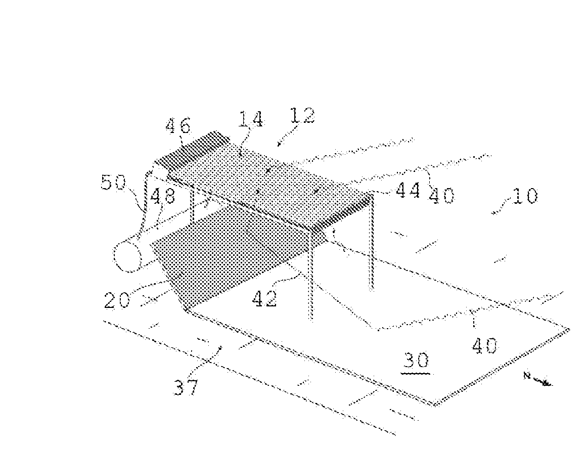
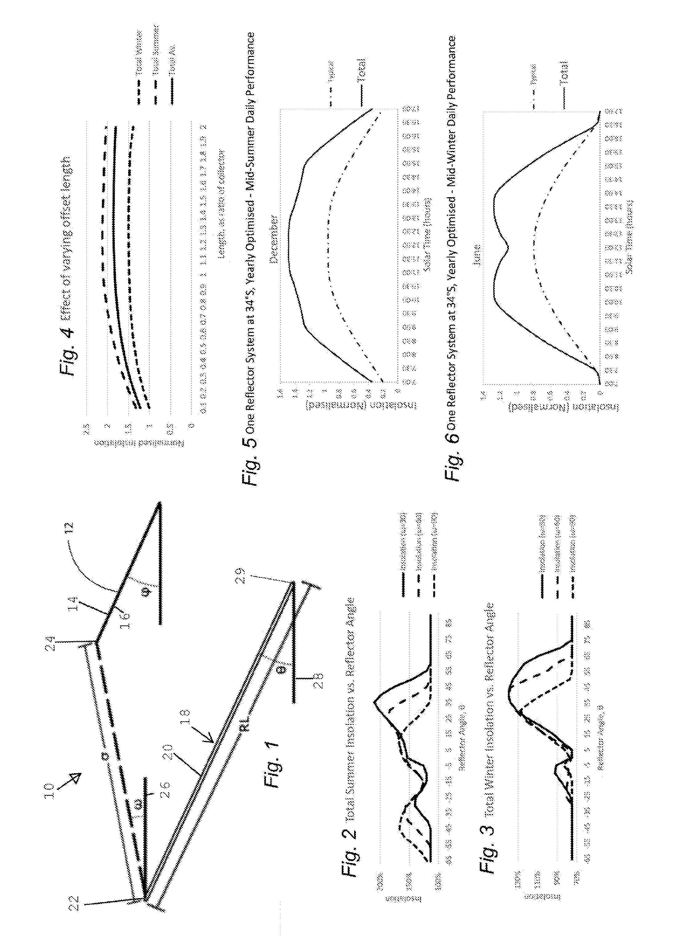
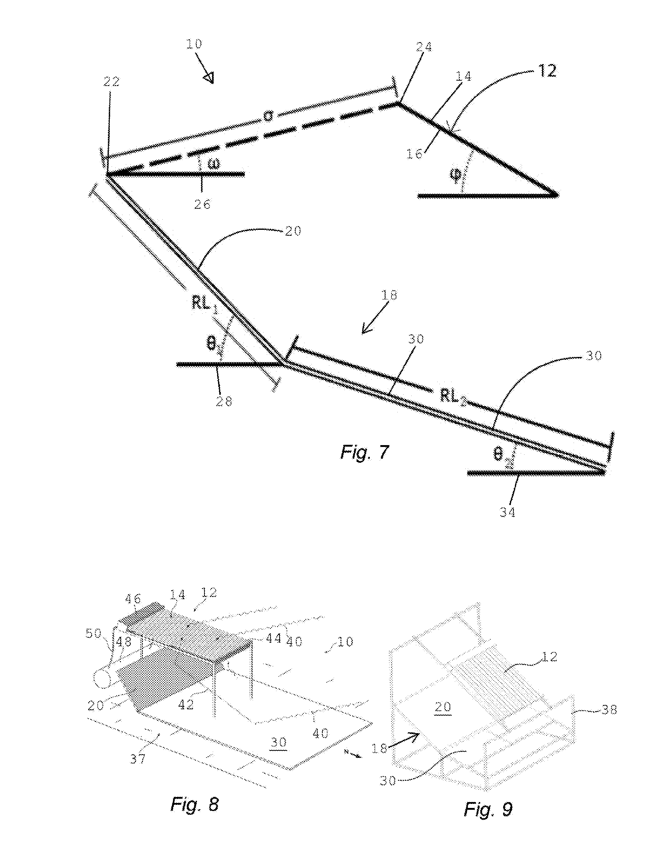
[0064]The following detailed description of the invention refers to the accompanying drawings. Wherever possible, the same reference numbers will be used throughout the drawings and the following description to refer to the same and like parts. Dimensions of certain parts shown in the drawings may have been modified and / or exaggerated for the purposes of clarity or illustration.

[0065]It is to be understood at the outset that reference to “reflector”, “reflective surface”, “reflecting surface”, “reflective face”, “reflective portion” or “reflective panel” herein are reference to the same or like feature being a surface, panel, etc, intended to reflect radiation. Likewise, reference to “collector” or “collector panel” are reference to the same or like feature being a collection surface tube(s), device, panel(s), etc, for collecting solar radiation. Reference to “planar” herein is intended to describe a characteristic of surface that does not focus solar radiation. Reference to “un-aug...


PUM


Abstract

The present invention relates to a solar energy collection apparatus and design method. In particular, the invention provides a solar energy collection apparatus incorporating one or more reflectors and a solar collector for receiving incoming solar radiation, including reflected radiation from the one or more reflectors, wherein the one or more reflectors and the collector are oriented according to a pre-calculated offset length and offset angle based at least on the latitude of the apparatus. The invention further provides a computer-implemented method of designing a solar collection apparatus including determining the optimal offset length and offset angle between the one or more reflectors and the collector for a given latitude and other inputs.

Description

FIELD OF THE INVENTION[0001]The present invention relates in a solar energy collection apparatus and design method. The invention further provides a computer-implemented method of designing a solar collection apparatus.BACKGROUND TO THE INVENTION[0002]Solar energy collators have been used for many years as a source of renewable energy using solar irradiation, otherwise known as insolation, to heat a fluid passing over a surface or through a conduit, or to provide solar insolation to other devices that collect heat for useful purposes. The collectors are typically supported directly above a roof and are angled by virtue of their mounting, or include frames to angle the collectors appropriately above a horizontal surface. A challenge in this field is to achieve a highly efficient conversion of solar radiation to thermal energy and to increase the temperature of the fluid to an extent that ensures the utility of the fluid is improved for various energy consuming processes.[0003]Solar t...

Claims


Application Information

Patent Timeline
Patent Type & Authority Applications(United States)
IPC IPC(8): F24J2/16G01J1/42G01B11/26F24S23/77
CPCF24J2/16G01J2001/4266G01J1/42G01B11/26F24S10/70F24S23/77F24S2023/876F24S2201/00G02B19/0019G02B19/0042Y02B10/20Y02E10/40
Inventor DAVIES, ROGER PHILIP
Owner INTEX HLDG
Why Eureka
Try Eureka