Bridging solar cell and solar energy system

a solar cell and solar energy technology, applied in the field of bridging solar cells and solar energy systems, can solve the problems of increasing the cost of solar energy systems, adversely affecting energy loss, increasing the power loss and material costs of the whole solar energy system, etc., and achieves the reduction of the total length of the used bussing ribbon in the solar cell module, the effect of improving the bridging solar cell

Active Publication Date: 2014-09-09
AU OPTRONICS CORP
View PDF5 Cites 0 Cited by
  • Summary
  • Abstract
  • Description
  • Claims
  • Application Information

AI Technical Summary

Benefits of technology

[0010]In order to solve the problems of the prior art, the disclosure provides an improved bridging solar cell. Particularly, the direction along which bus bar electrodes are disposed on a back surface (which is referred to also as a shadow-side surface in the disclosure) of the bridging solar cell is different from the direction along which bus bar electrodes are disposed on a front surface (which is referred to also as an incident light-side surface in the disclosure) of the bridging solar cell. Therefore, the foregoing bridging solar cell can be used to electrically connect two solar cell strings in a solar cell module. The bus bar electrodes on the back surface of the bridging solar cell can be directly extended onto a front surface of another bridging solar cell in another solar cell string and act as the bus bar electrodes on the front surface of the another bridging solar cell, and so it is unnecessary to electrically connect the solar cell module to an external element (i.e., to another solar cell module) using bussing ribbons disposed at a region adjacent to an upper edge and a region adjacent to a lower edge of a glass substrate of the solar cell module. Accordingly, not only can the area of the glass substrate of the solar cell module be reduced, but the total length of the used bussing ribbons in the solar cell module can also be reduced, so as to achieve the advantages of saving costs of related materials and minimizing energy loss.
[0017]The disclosure further provides an improved solar energy system. Particularly, the direction along which two sets of bus bar electrodes are disposed on a back surface of a bridging solar cell is different from the direction along which bus bar electrodes are disposed on a front surface of the bridging solar cell. Therefore, one set of bus bar electrodes on the back surface of a bridging solar cell of a solar cell string of a solar cell module can be directly extended onto a front surface of another bridging solar cell in another solar cell string of the solar cell module and act as the bus bar electrodes on the front surface of the another bridging solar cell when the solar cell strings are made to be electrically connected in series. Moreover, another set of bus bar electrodes on the back surface of the bridging solar cell of the solar cell string of the solar cell module can be electrically connected to another bridging solar cell in another solar cell module by using welding members and a junction box. Accordingly, not only can the area of the glass substrate of the solar cell module be reduced, but the total length of the used bussing ribbons in the solar cell module can also be reduced, so as to achieve the advantages of saving costs of related materials and minimizing energy loss.

Problems solved by technology

As a result of this configuration, the power loss and material costs of the whole solar energy system are increased.
Ultimately, energy loss will be adversely affected.

Method used


Image

  • Bridging solar cell and solar energy system
  • Bridging solar cell and solar energy system
  • Bridging solar cell and solar energy system

Examples


Embodiment Construction

[0029]Reference will now be made in detail to the present embodiments of the disclosure, examples of which are illustrated in the accompanying drawings. Wherever possible, the same reference numbers are used in the drawings and the description to refer to the same or like parts.

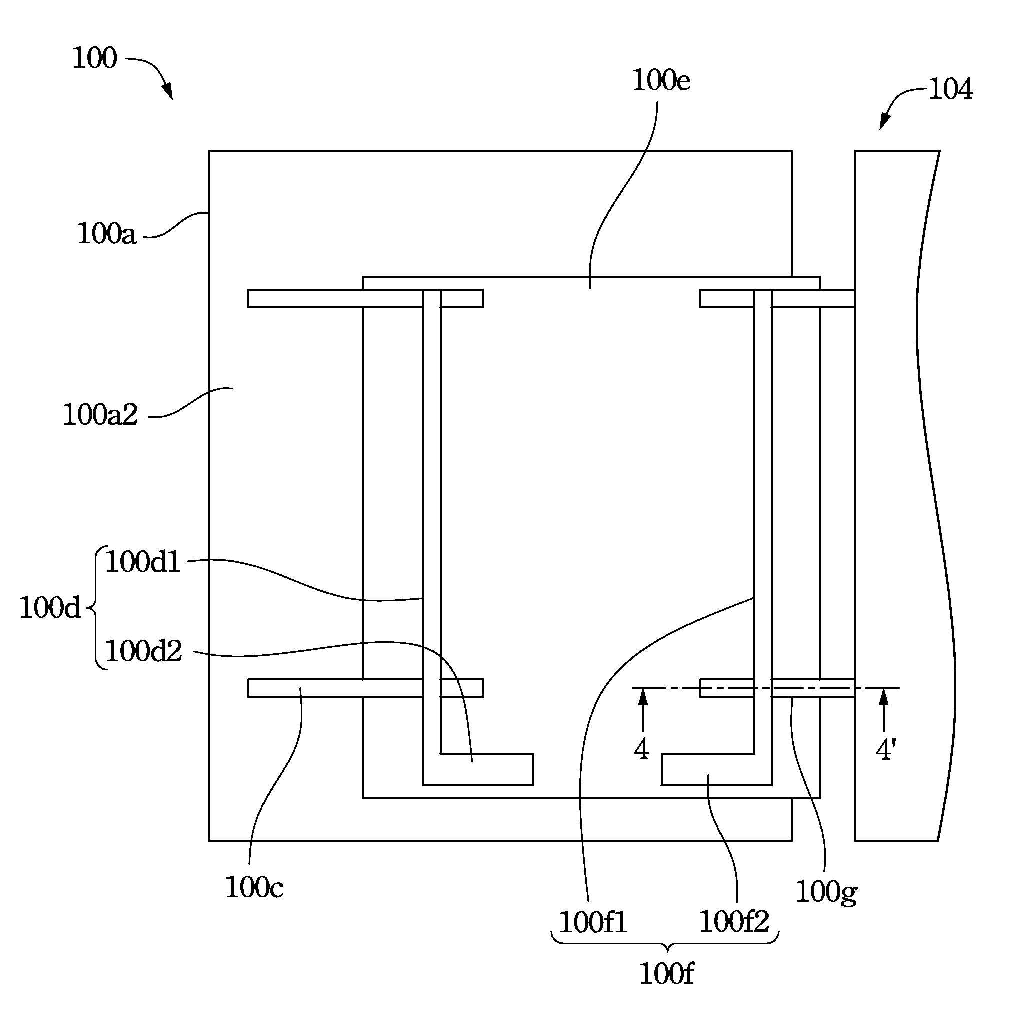
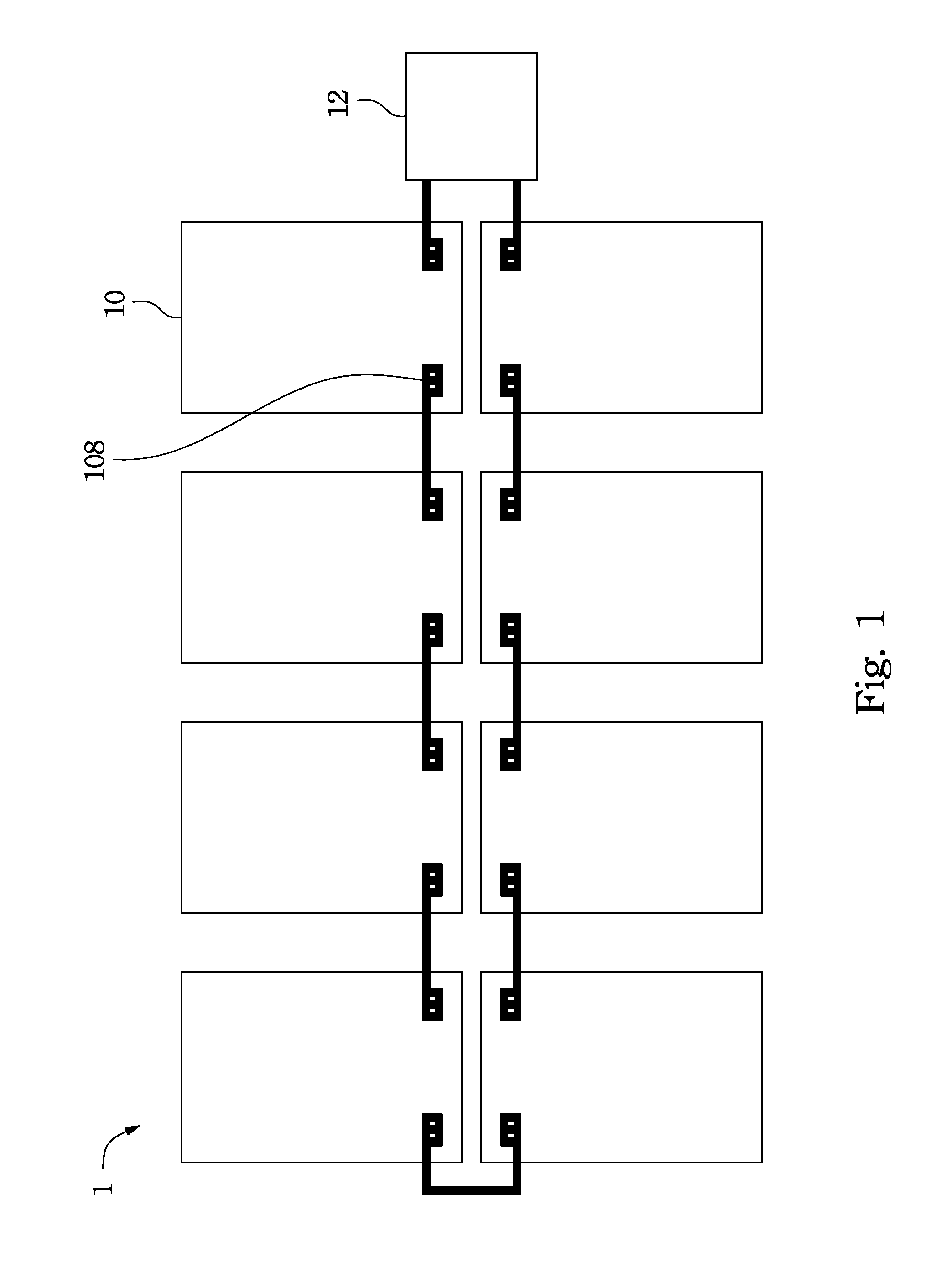
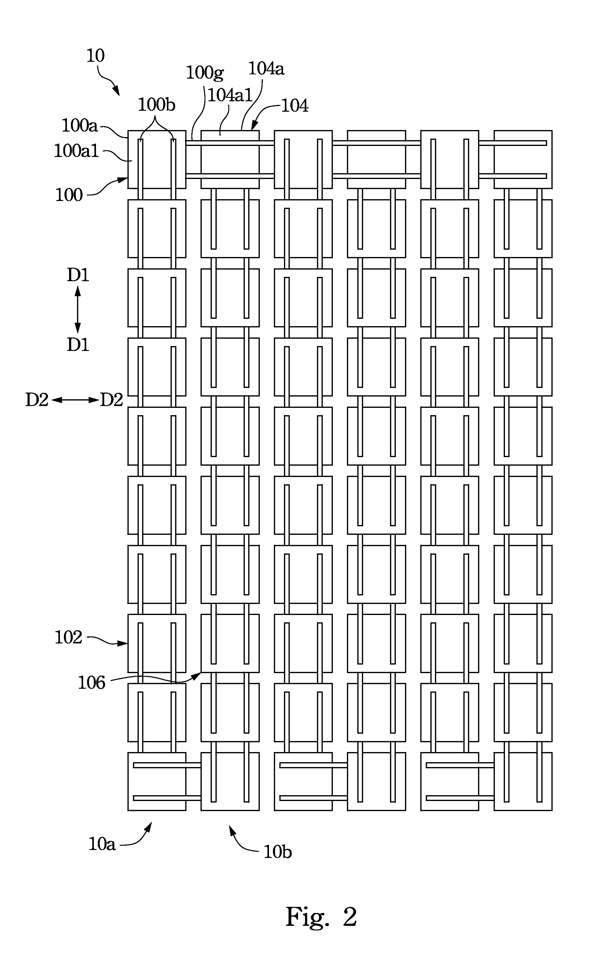
[0030]An improved solar energy system is provided. Particularly, the direction along which two sets of bus bar electrodes are disposed on a back surface of a bridging solar cell is different from the direction along which bus bar electrodes are disposed on a front surface of the bridging solar cell (e.g., the direction along which the sets of bus bar electrodes are disposed on the back surface of a bridging solar cell is perpendicular to the direction along which the bus bar electrodes are disposed on the front surface of the bridging solar cell). One set of bus bar electrodes on the back surface of a bridging solar cell of a solar cell string of a solar cell module can be directly extended onto a front surfa...


PUM


Abstract

A bridging solar cell includes a substrate, first, second, and third sets of bus bar electrodes, a first welding member, a first insulation film, and a second welding member. The first set of bus bar electrodes is disposed on the front surface of the substrate along a first direction. The second set of bus bar electrodes is disposed on the back surface of the substrate along a second direction and electrically connected to the first set of bus bar electrodes. The first welding member is electrically connected to the second set of bus bar electrodes. The first insulation film is disposed on the back surface. The third set of bus bar electrodes is disposed on the first insulation film along the second direction. The second welding member is disposed on the first insulation film and electrically connected to the third set of bus bar electrodes.

Description

RELATED APPLICATIONS[0001]This application claims priority to Chinese Application Serial Number 201210165275.1, filed May 24, 2012, which is herein incorporated by reference.BACKGROUND[0002]1. Technical Field[0003]The present disclosure relates to a bridging solar cell and a solar energy to system.[0004]2. Description of Related Art[0005]Owing to the shortage of fossil fuels, awareness of the importance of environmental protection is increasing. Therefore, many have been actively developing technologies related to alternative energy and renewable energy in recent years, with the hope that the dependence on fossil fuels and the impact on the environment caused by using fossil energy can be reduced. Among the various kinds of technologies related to alternative energy and renewable energy, the solar cell is a technology that is receiving much attention. The reason for the interest in this technology is that solar cells can directly convert solar energy into electricity, and carbon dio...

Claims


Application Information

Patent Timeline
Patent Type & Authority Patents(United States)
IPC IPC(8): H01L31/00H01L27/142H01L31/0224H01L31/042H01L31/05H02S10/00
CPCH01L31/022433H01L31/0504H01L31/0508H01L27/1426H01L31/0201H01L31/042Y02E10/50H01L31/0465H02S40/36Y02E10/547
Inventor TSENG, HUANG-CHIYANG, CHUN-MING
Owner AU OPTRONICS CORP
Why Eureka
Try Eureka